Case Study: Covering Up (01 Intro)

Covering objects, removing the cloth covers, and playing with the wind.
Cloth Room without Clothes.

Download this tutorial in PDF format (1.7 Mb).
Download a set of Bagginsbill’s cloth squares (X-tris only).

Introduction and Preparation

In this Case Study I’ll present some basics from Poser Cloth Room. I’m going to use pieces of cloth to cover objects, and to use as flags and banners. I also will introduce some animation, like moving objects, waving flags and using wind.

To save you the time finding or making decent pieces of cloth, I’ve included some in the package that also contains this PDF. Credits to BagginsBill who presents a far larger package for study purposes on his own site

http://sites.google.com/site/bagginsbill/free-stuff

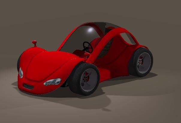
To start, I’ll open Poser, delete the default figure (select it and click [Del]), and ensure I’ve got a ground plane and some light. Then I add an object to the scene, say a car.

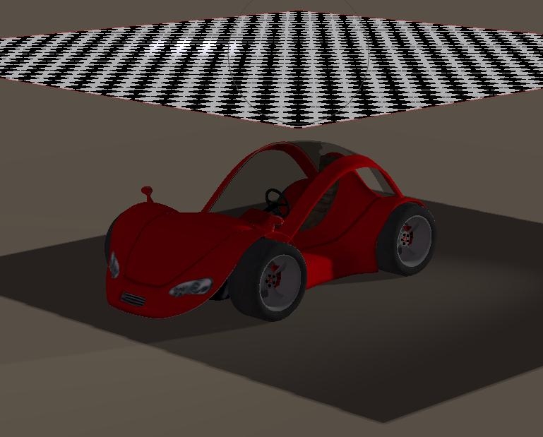
To add a piece of cloth, I can just open the (Windows) Explorer, pick the piece I like and drag it into the scene. I like the 3m sized cloth with a 20mm resolution, which contains (300cm/2cm)2 = 22,500 vertices. When you experience performance issues on your machine, you can take a smaller cloth with a lower resolution (as the 2m cloth at 40mm contains (200/4)2 = 2500 vertices, a tenfold less. Which of course will give you coarser folds and wrinkles.

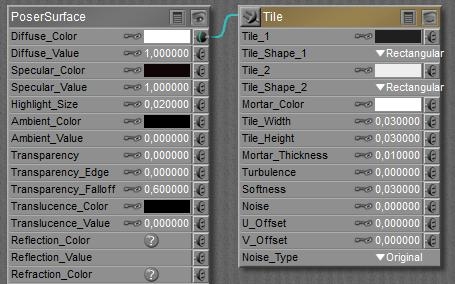
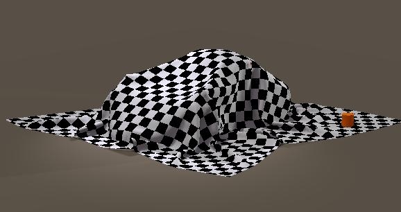
I scale the cloth to 250% to ensure it can cover the car properly, and I give it a blocked texture to reveal to folds and wrinkles.


I put the cloth somewhat above the car, I’m done with preparations, and enter Cloth Room.

Case Study: Covering Up (02 First Drape)

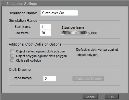
In Cloth Room, I create a [New Simulation…] (panel 1), give it a meaningful name and accept all other default values.

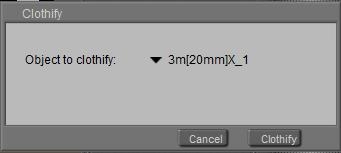
With the cloth selected, I click [Clothify…] (panel 2) to define the cloth object,

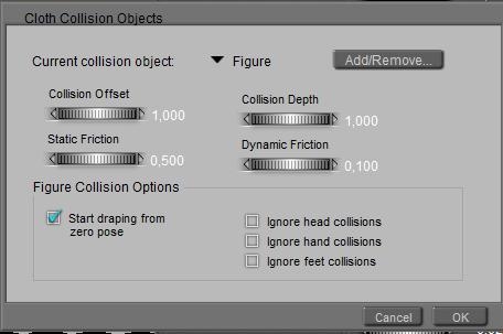
and I click [Collide Against…] to define the collision objects.

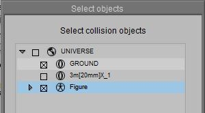
I use [Add/Remove…] and check Car and Ground, accept with [OK]

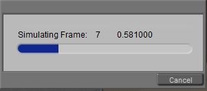
and continue with [OK] to accept all other default values. Now I [Calculate Simulation] (panel 4).

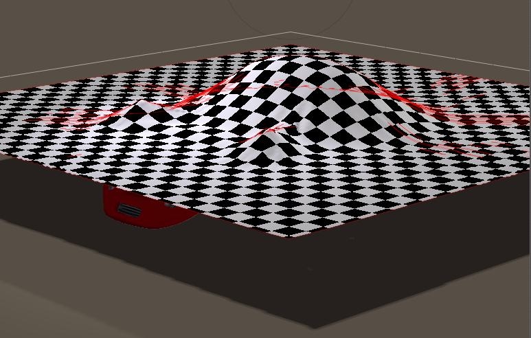
I see the cloth fall onto the car (the message tells that while calculating frame 8, the previous one took about 0.6 sec), and I can start to analyze this first result. Save your file.

Case Study: Covering Up (03 Second Drape)

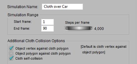
From the first result I see that the cloth needs more time to settle, and in [Simulation Settings…] (panel 1) I extend the 30 frames (1 sec) to 90. And I [Calculate Simulation] again.

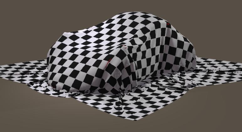
Now I see the car poking through (some red spots), and I do have my doubts about the quality of the folds.

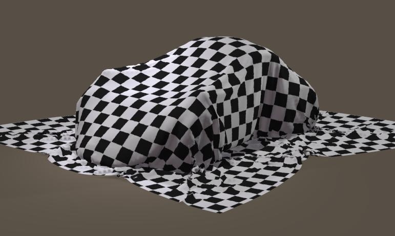
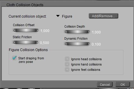
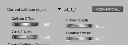
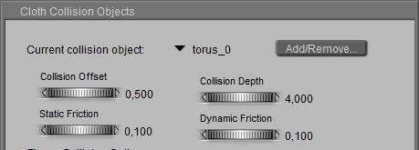
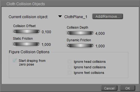
So I adjust the [Simulation Settings…] another time. By checking the first (Object vertex…) option – always the first step in improvements, by checking the third (Self-collision) option to prevent the cloth to fold into itself, and I double she Steps per Frame from 2 to 4 to refine the calculations. That’s fine, I did not need the 2nd option. The more options I check the more time it takes to complete a proper simulation. The collision options don’t need a change at all. Let’s peek behind the [Collide Against…]. The little triangle lets me choose between the collision objects Figure (aka the Car) and Ground. The Offset reads 1, that is: the cloth will remain 1 cm from the car. The Depth needs attention only when the cloth and car are moving rapidly towards each other which might introduce artifacts (not the case now), Friction is meaningful when cloth and car slide along each other, and the options are meaningless as the car is not a character, and hence has no ‘zero pose’ nor a head, hands or feet. Save your file.

Case Study: Covering Up (04 Third Drape and Save)

The 1 cm offset represents quite a thick kind of cloth, while the folds and crumbles on the ground are quite fine. Actually, I like a bolder impression of the material. Actually, Poser default cloth represents fine silk, which is known for high air damping (it gently floats down) and for low resistance values (silk folds very well). So, for my bolder impression, I increase the resistances and reduce the air damping, and I take serious steps doing so to get the noticeable results.

Default My settings
Fold Resistance 5 50 or 500
Shear / Stretch Resistance 50 250
Stretch Damping 0.01 0.1
Air damping 0.02 0.002

The first thing I notice is that the entire cloth folds onto the ground at about frame 20, much earlier as in the first run. This is due to the reduced air damping: the cloth floats less and falls faster.

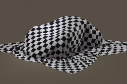
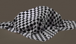
Second, the “look and feel” of the cloth is mainly determined by the Fold Resistance parameter. Here you can see it raised from 5 to 50 (left) and then to 500 (right). The latter is the real heavy stuff.

Now, select the cloth as well as the latest frame in the simulation range

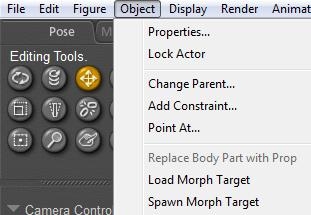
Click menu Object > Spawn Morph Target (give the result a decent name, like “Cloth over Car”)


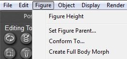
Followed by menu Figure > Create Full Body Morph (you can use “Cloth over Car” again)


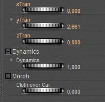
The first step defines the shape of the cloth as a morph target, the second creates a Morph Dial in the cloth properties (Pose Room):


To see the effect of this, [Clear Simulation] in Cloth Room, go back to simulation / time frame 1, change to Pose Room and change the Morph dial from 0 (flat cloth floating above the car) to 1 (cloth neatly folded as resulted from the simulation). We’ve frozen the sim results. Save your file.

Case Study: Covering Up (05 Pin and Move I)

Now I’m going to have fun with some animation. First, in Pose Room, I set the time slider to frame 1, and hide the cloth (properties, check Visible OFF). Then I select the car, move the slider to frame 30 and I move the car 6 to 7 meters in Z direction. I don’t care about rolling the wheels, that’s for later refinement when I’m up to it. Back to frame 1, and I unhide the cloth again.

After ensuring that the Cloth over Car morph dial is set to 1, I switch to Cloth Room and click [Edit Choreographed Group…] in panel 3. This opens the Group Editor, and I pick a few vertices from the cloth. The editor can be closed with the (red crossed) close button in the upper right corner.

The vertices we’ve just selected will be excluded from the cloth sim calculations, but will follow the preset movements of the cloth itself. If the cloth was animated like the car, those vertices would follow that animation (hence the name: choreographed). At the moment however I’ve not animated the cloth, and therefore the vertices in the Choreographed group will stay put while the car drives forward, underneath the cloth. I only have to [Calculate Simulation…] to make it happen. And wait a while, as most frames seem to take about 10 sec each, and I’ve got 90 of them (that makes say 15 mins, depending on your computer speed).

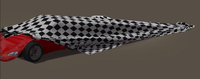
To view the result properly I’ve got to switch to Pose Room and set the Cloth over Car morph to 0. At frame 30 the result is like:

And that one spot seems glued to the ground.

So the cloth stretches a lot and then contracts while slipping off the car. I also see the Fold Resistance is 50.
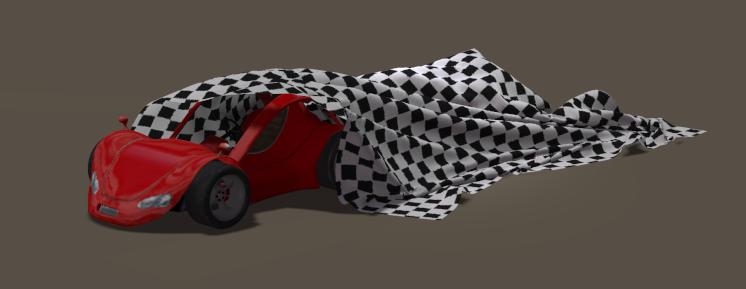
So I set Fold Resistance to 500 to make the thick cloth with the fat folds, and I raise Stretch Resistance to 900. Another way is to reduce the Friction parameters to make the cloth slide easier over the car. I [Clear Simulation], I ensure that the Cloth over car morph reads 1 again, and I [Calculate Simulation…] again. When done, I set Cloth over Car morph to 0 (Pose Room), select frame 20 as it shows a fun result and render. This is it:

and you see that the cloth stretches far less, and sort of jumps from the car. When you want, you can enhance the scene by putting a pylon, or a high heeled girl, right onto the glued spot as if that object or figure is nailing the cloth down while the car drives away.
By using menu Object > Spawn Morph Target and menu Figure > Create Full Body Morph at say frame 90 you can freeze the sim result again.

Case Study: Covering Up (06 Pin and Move II)

As freezing some vertices in the cloth is quite an artificial way to create a result, the question is: what’s the alternative? What happens when I just put a heave object upon the cloth? Let’s find out.

First, I clear the groups in the cloth by [Edit Choreographed Group…] and clicking [Remove All]. This empties the group, and all vertices will join the simulation again.

Then (from Pose Room) I put a small (cylinder) object upon the cloth

Second, back to Cloth Room, I add this object to the set of collision objects, using the [Collide Against] (panel 2). In that same window, I select (using the small triangle) this object, and I set both Friction parameters to their maximum: 1.0. Then I select Ground, and I do the same.
I leave the car to its defaults.

Third, I give myself the proper start position with [Clear Simulation] and by setting the proper Morph dial to 1.

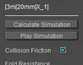
And, in the cloth properties panel, I check the Collision Friction option. This tells the simulator NOT to use the values below from the cloth object, but to use the values from the collision objects instead. And that means that the clot will experience extreme frictions from ground and pylon object, and default friction from the car.

[Calculate Simulation…] does the job again, and viewing the proper result might require to set the Morph dial to 0 afterwards (Pose Room, frame 1).


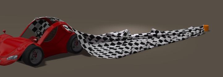
My result looks like this:

Not too bad. Actually the frictions for the car a somewhat high so the cloth gets pulled forward even at the extreme frictions between the cloth and the car and ground. Frictions apparently do not stop all sorts of movement.

Frankly, the 0.1 dynamic friction is quite high for cloth sliding over a well lacquered steel car roof anyway, and so is the static friction of 0.5. Both can be lowered at our liking, but when doing so it has to be done in the Collision Objects collection as the sim uses that info instead of the friction from the cloth parameters.

Case Study: Covering Up (07 Banner and Flags)

Let me show some basics on banners and flags. First I drag and drop a decent piece of cloth onto an emptied Pose Room:

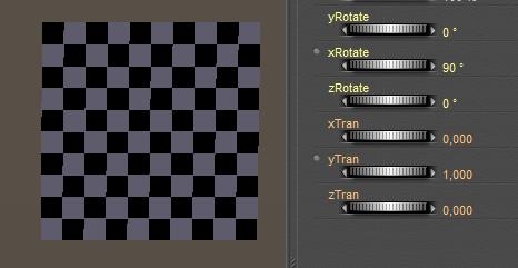
Then I put it in position (xRot=90, yTran=1 mtr) and assign it neat material. After switching to Cloth Room I create a [New Simulation…] (panel 1) and I [Clothify…] (panel 2) the sheet. There is nothing to [Collide Against…] so I can leave that one, I only need to [Edit Choreographed Group…] (panel 3).

I decide just to select to top corner areas:

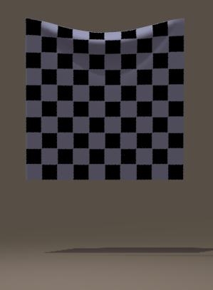
And now I can [Calculate Simulation…] for the first run. Perhaps I like a more flexible banner. I can do that by reducing all the resistances (friction and air damping won’t affect the result anyway). But instead, I can increase the Cloth Density as well, tenfolding to 0.05 for instance. The magic here is that the result is determined by the ratio of <parameter>/density, so reducing all parameters, or just increasing density, have a similar effect.

Variations to this theme are: adding more points to the Choreographed Group, or adding the complete top row of vertices to it. Using only one corner turn the banner into a towel, which I can hang onto a wall or so. And, for a change, I can put both sides into the group, rescale (in Pose Room), and reset the Cloth Density to its original 0.005 :

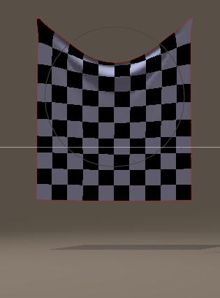
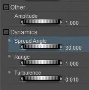
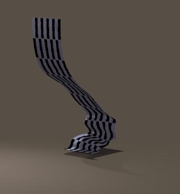
When to cloth continues to wobble up and down, I need more frames (in Simulation Settings, try 90) and/or I have to pump up the Stretch Damping to say 0.1: When banners are hanging outside, the wind will play with them. Let’s see how that works out in Poser. By now, we know how to hang a banner (top row of vertices in the choreographed group) and prepare it for simulation. In panel 4, [Reset] will bring back the default values (except for Stretch Damping, a Poser bug still not fixed in P9/PP2012 SR2. It’s not you). I can make a test simulation if I want to, to check the effects of the settings. Now (in pose Room) I rotate the camera a bit to get some side view, and by menu Object > Create Wind Force I add a ventilator. Using the various camera position (Front, Aux, …) I position the ventilator somewhat at the bottom half of the banner. I also set the parameters:

Amplitude is left at its default: 1,
Spread Angle is reduced to 30, it narrows the stream bundle width,
Range, beyond that no winds will blow so it has to reach beyond the banner at least,
Turbulence, just a bit for the fun of it.

And now, in Cloth Room, I can [Calculate Simulation…].

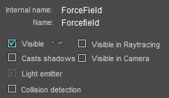
In most cases, the source of the wind is not what should be seen in the render, so I uncheck the visibility options in its properties. And render the result.


<= hanging vertical banner with wind.

Now, let’s discard the entire Choreographed Group which keeps the top of the banner in place. Then the banner will fall, while the winds are blowing. In the editor (Cloth Room, Edit Choreographed Group) I [Remove All]. And…


I have to add the Ground for a Collision Object (panel 2, Collide Against, check Ground). Otherwise, the cloth will fall right through it. Then, [Calculate Simulation…] again:

Note that even when the cloth is completely on the ground, the wind will keep blowing it away depending on the (dynamic) friction, until the cloth is out of range of the ventilator.


WARNING: in Poser 9 / Pro 2012, Service Release 3 (SR3), the Wind Generator in Cloth Room is BROKEN. You won’t get any effect. It’s not you, it’s a software bug

Case Study: Covering Up (08 Finish flag)

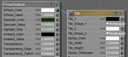
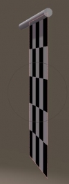
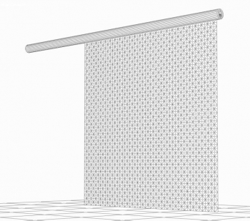
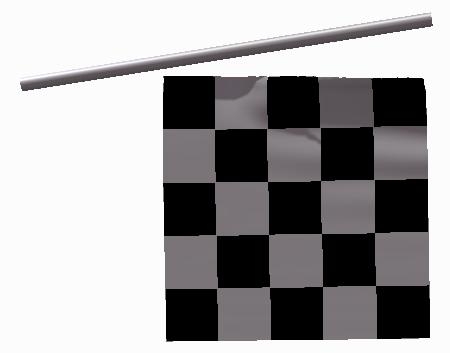
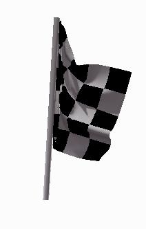
Since the car has escaped its covering cloth (see the Pin and Move II section), let me create a finish flag. So I import (or drag and drop) the 1×1 mtr X-tri cloth (in the download), give it a Black & White tile material:


and put it in upright position. I also get a standard Cylinder (Library, Props, Primitives) which I scale into a flag pole (20% overall, then 3000% in Y) and put in such a position that it intersects with the top vertices of the flag.

The next step is to animate the pole, and after that I’ll use Cloth Room to drag the flag with it. Pole first.

In the properties pane, I select my camera and switch off Animating, so I can freely move without seeing that back into my result.Next I set the pole: zRot = -90 at frame 1, zRot=0 at frame 30 and zRot =-90 again at frame 60.

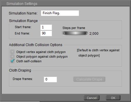
In Cloth Room, I create a [New Simulation…] (and call it Finish Flag for the sake of it) with the end frame set to 90 as I need 60 frames (2 sec) for the pole to animate, and then I like another second (30 frames) for the flag to come to rest. This might look better when I’m repeating the final result.

Since (see the wireframe) the cloth polys are fine compared to the pole I might not need the extra collision options but the waving flag will collide onto itself, especially around frame 30 when the flag still is going up somewhat while the pole is coming down already. I don’t need extra drape frames at the start.

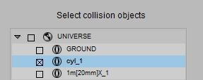
Then I [Clothify…] the flag, make it [Collide Against…] the pole, and leave all other settings to their defaults.


Now I have to fetch the flag to the pole, in such a way that the top vertices of the flag behave like nailed to the vertices and polys of the pole. The pole is in the collection of Collision objects, so putting the flag vertices in the Constrained Group will do.

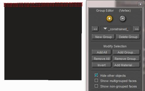
[Edit Constrained Group…] opens the editor, and checking Hide other objects gets the pole out of the way for the moment. I select the top three rows (the pole and flag intersect somewhere between row 2 and 3), uncheck the Hide objects and close the editor.
Note: when I forget to uncheck the Hide option I might need to make them visible again by using their own Properties setting, which might end up quite tedious when there are a lot.

For this demo I leave the cloth properties in panel 4 at their defaults (fine silk-ish), save the scene, and [Calculate Simulation].
It might come as a shock, but the flag falls off immediately. The Constraining seems to be without effect.

Now I do have two options:

  • Animate the flag itself
  • Change the pole

Animate the flag

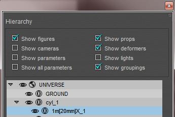
I [Clear Simulation] in Cloth Room, enter Pose Room, select the flag, goto frame 1, open the (menu Window >) Hierarchy editor and I drag the flag under the pole:


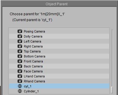
This makes the pole the Parent of the flag, and the flag the Child of the pole. Hence it will follow it’s movements.
An alternative way to do this is: menu Object > Change Parent (NB: menu Figure . Set Figure Parent won’t work as the flag is a prop, not a figure).

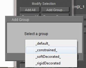
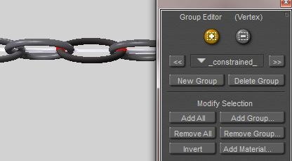
Now I have to tell Poser that some vertices of the flag should not follow the dynamics simulator, but should follow its animation (which results from following its parent, the pole). So, in Cloth Room, I [Edit Choreographed Group…], I click [Add Group] and I select the _constrained_ group. This puts the previously marked vertices into the other group.

To avoid confusion, I also [Edit Constrained Group…] and click [Remove All]. Actually, as each vertex should be in one group only, I would expect this group to be empty after the transfer but apparently Poser it not working that way when using the Modify Selection buttons. Maybe a bug, maybe a feature J.

Anyway, after [Calculate Simulation] I get the result I wanted, as the figure at the left shows (frame 33).


Change the pole

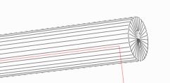
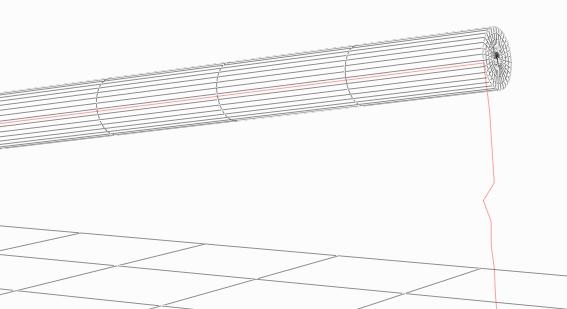
When you look closely to the wireframe of the pole, you will notice that it offers some vertices at the caps, but the main body is a set of very long polys from one end to the other, without any intermediate vertices. So when the vertices of the flag in the Constrained group look for pole-vertices to track, they hardly can’t find any. The constraining is a (cloth) vertex to (collision object) vertex relationship, not a poly-to-poly or a body-to-body one.
In other words: I want to nail the flag to the pole, but no nails are used. So I can look in the Library for a cylinder with several intermediate points, and shorter polys along the body. In Poser 9 / Pro 2012 the Morphing Cylinder prop is a nice one. It needs some extra care as the point of rotation is in the middle and not at one end so is has to be shifted first, but okay.

As you can see, it does not offer that much extra vertices and after [Calculate Simulation] I do find some improvements, but not that much. The flag is nailed to the pole but given all the forces on the flag, this small amount of nails can hold the flag for just a few frames only.

Conclusion
When using Constrained grouping, ensure that the cloth vertices meets enough object vertices to make the constraining actually happen. Objects with a low mesh-density or areas with large polys make the constraining hard to establish.

But as I illustrated, a simple animation of some vertices in the cloth can do the job as well, in some ways. And I illustrated the use and differences between the constrained and the choreographed groups.

Case Study: Covering Up (09 Simple Examples)

In this chapter I’d like to demonstrate some simple uses of cloth simulation.

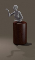
With a statue, where I did exclude and include the figure in the set of collision objects:

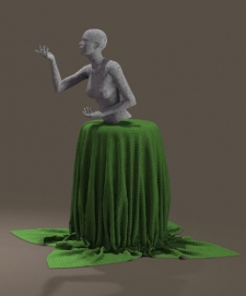
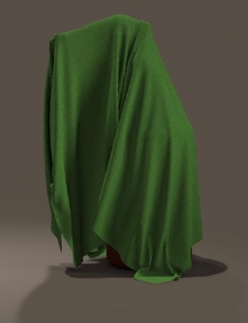
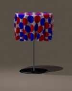
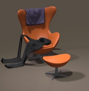
A table, covered with the round HighRes TableCloth (standard Poser 9/Pro 2012 Library prop), and some clothes thrown over a chair. Just drag them in place and – literally – drop them.

Case Study: Covering Up (10 Advanced Examples)

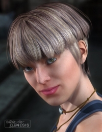
Clothifying hair

Cloth simulation might be a way to turn Conforming Hair into Dynamic.

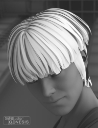
Luka Hair, by SWAM (2012).
Conforming hair strokes can be turned into dynamic by treating them like cloth. This make them bounce in animation, and swirl in the wind.

The large amount of fine hair strokes might bring a lot of work when I’d like to clothify them all (separately) but the fine structure might work out quite well in not too extreme conditions.

And… why should I clothify all strokes, perhaps I can do with the top ones only.

A Chain of Links

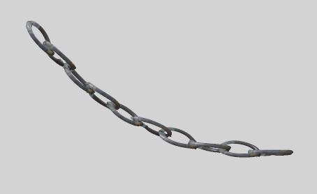
In the finishing part of this tutorial, I’ll make a swaying chain of iron links:

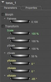
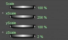
The links themselves are simple Torus primitives, which I shrunk a bit, opened up (zScale 50%, fatness 0,1) put in a row and I rotated the even ones a bit as the objects could not intersect:

This started the journey along the ways that could turn this series of links into a swaying chain. I will tell you about the mishaps first, and finish with a reasonable successful one.

Simple Clothifying

I open Cloth Room, start a [New Simulation…] and use [Clothify…] on all links 1..9, while the first (leftmost) link #0 is marked a collision object using [Collide Against…]. The alternative is clothify that one too but to put it completely in a choreographed group (which will freeze it, as I did not apply any animation on it).

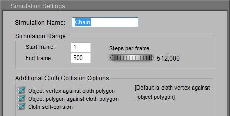
The idea is that the links will fall (except #0) and each link 1..9 is stopped doing so by the link next to it. As all clothified links are considered pieces of the same one cloth, I’ll need to check the Cloth self-collision option in the [Simulation Settings…].

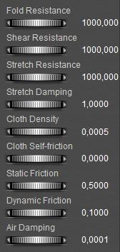
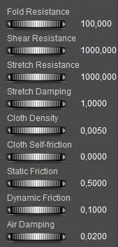
I also must turn the clothified links into steel ones: stiff compared to their density (mass), and dense compared to the world around them. So I raise the various Resistances to their max, while reducing Air Damping considerably.
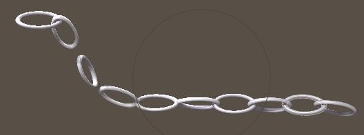
When running the sim, I found out it did not work. The first clothified link did stick to the collision object link left to it but the chain broke at the next link. This means that the chain is moving too fast for the simulation to handle the collision, and pumping up the Steps-to-Frame settings in the [Simulation Settings…] is actually the only way out. But to what extent?

The image above shows the result of Steps set to 128 (the sim takes 10 sec/frame) and further testing reveals that Steps set to 512 (40 sec/frame calculation time) only improves the result a little bit.

Altering the collision parameters has no effect, as these concern the interaction between the clothified objects and the collision objects only. And the breaking chain shows that the issue is in the interaction between the clothified objects themselves. 


So, this is not the way.

The Helper Object

My next attempt introduces a simple, long and small cloth plane: the Stripe.

I put the leftmost vertices in a Choreographed group to fixate the Stripe in space, and I gave it the maximum Resistance parameter values similar to the steel links, except for Folding to prevent it from behaving like a steel plate.

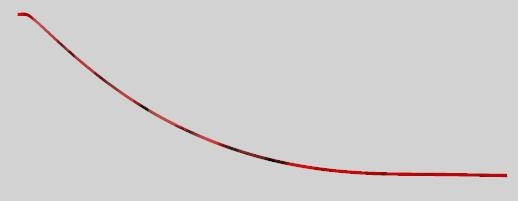
Then I ran the sim calculations and found out I needed say 600 frames to give a full right-left-right sway to this stiff object.


Now the question was: how do I connect the steel links to it? I can

  • Parent them to it
  • Attach them as (hard) decorated groups
  • Constrain them to it

Parenting the Links
So I made the Stripe the parent object for all Link objects. Would they follow the movements of the Stripe?

No, they did not, for a simple reason. Parenting implies that the rotation, scaling and displacement of an object as defined by its local origin and axes follow the same of its parent object defined by its local origin and axes. But… the sim calculations do not rotate, scale or displace the Stripe object as such. They produce a morph, displacing all the individual Stripe vertices relative to the Stripe’s local origin and axes, but the local origin is left untouched.

As a result of that, the Link objects are not going to move either. This is not the way.

Decorating the Stripe
Now I used the sim for the Stripe, added all Links to it while clothifying them all. Then I put all vertices in a (Rigid) Decorated group, for each Link. So, actually the sim works on the Stripe, and the Links were expected to follow.
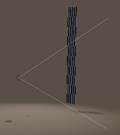
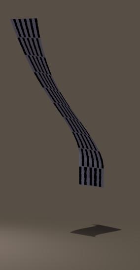
Well, in my simple test they did not. The point is, a piece of cloth and its decorations are expected to be one 3D mesh. They should not share vertices not should assigning vertices to the Decorated group leave holes in the cloth, but there should be some edges in the mesh connecting them. Like a button on a jacket: both are separate but a little thread stitches them together and prevent the button from falling off.

In this case, the stitching thread is missing. The Stripe and the Links are separate objects, and there are no edges connecting vertices of the one to the other.

Constraining the Links

Next idea: what if I treat the links as individual, clothified items like I did at the start, but let each of them follow the chain-stripe the closest as possible? That means: next to the sim which creates the movements of the stripe, I make a second sim containing all the links, and contains the stripe as a collision object. Each link then has a serious Constrained group, relating the link to the stripe. Since this relationship is used at the vertex level, the links can be expected the movements and deformations of the stripe to the closest. At the same time the links are not really hanging to each other anymore (or at least far less), which might prevent the issues mentioned previously.
To prevent the links from slipping along the strip I raised the Frictions, and while I kept on having issues with links snapping off, I solved them by raising the Collision Depth (and altering the other settings as well)

Of course the sim had to be as long as the movements of the chain stripe (600 frames). As I kept having links with intersecting polys (not believable for steel), and snapping off during the sim, I checked the other options and started raising the Steps per Frame. Simple: the intersecting objects suggest that the speed at which they collide is too high to handle, so I have to consider smaller steps in the sim or: more steps per frame.

I ended up at 128 steps per frame. Each frame required about 40 sec to calculate with this amount of steps and all options switched on. Times 600 frames make 24,000 sec = 400 mins = about 7 hours. I do have a fast machine (i990 @4GHz) but this was a typical overnight run.

The result is okay, at least for the first 400 frames. From then on the links suffer noticeably from being clothified: they start getting a deformed shaped in quite an un-steel like way. But anyway, this ‘constrained to the stripe’ seems to be a promising approach. Wild and large chain movements might need some more elaboration, by my girls can wear a chain for a belt from now on. Simulate a normal cloth stripe (belt) first, then constrain the links to it and simulate the links.

For rendering, I gave the links a rough greyish material with some shine to suggest a rough steelish feel, and I made the stripe itself invisible as it’s a helper object after all.