Managing Poser Scenes (03. Camera Blur & Parameters)

Like a real-life camera, the Poser camera presents us: Focal or Lens Blur (sharpness limits), Motion Blur (speed limits), Field of View (size limits) and even more limits.

Focal Blur

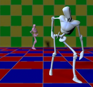
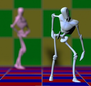
Focal Bur, or Depth of Field, is in reality the result of focal length, diaphragm (fStop) setting and shutter speed, while also fStop, shutter speed and film speed (ISO) are closely related. In Poser however, there is no such thing as film speed, and the Depth of Field is determined by the fStop setting only. Whatever the shutter speed, whatever the focal length, they won’t affect the focal blur.

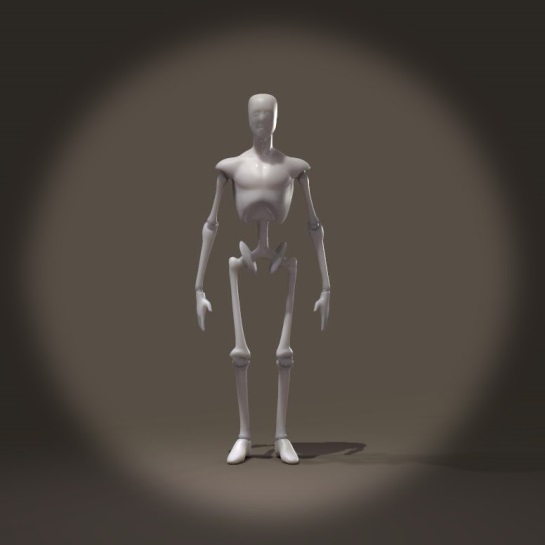
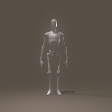
20 mm, fStop 1.4: 120mm, fStop=1.4:

In a real camera, the change in focal length would have brought Pink Andy and the back wall in a sharp state as well. In Poser, the blur remains the same. And because the back end of the scene is brought forward when enlarging the focal length, the blur even looks like it’s increasing instead of the other way around.

Motion Blur

Shutter Open/Close both have values 0 .. 1, Close must be later that Open. The shutter time is measured in frame-time, so if my animation runs at 25 fps the frames start at 0.00; 0.04; 0.08; then Open=0.25 means the shutter opens at 0.01; 0.05; 0.09 or: 0.25 * 1/25 = 0.01 sec after frame start. Similarly, Close=0.75 means that the shutter closes at 0.03; 0.07; 0.11 or 0.75 * 1/25 = 0.03 sec after frame start and therefor 0.02 or 1/50 sec after Open. Contraring to real-life cameras, shutter time does not affect image quality like depth of field, it only affects motion blur or: 3D / spatial blur, in animation but in stills too.

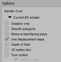
So, a shutter speed of 1/1000 sec translates to a 0.030 value in a 30 fps animation as 0.030 / 30 = 0.001. For stills without motion blur, I just leave the defaults (0 and 0,5) alone. For anything with motion blur, I should not forget to switch on 3D Motion Blur in the Render Settings.

More parameters

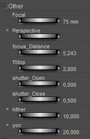
The other two parameters: hither and yon, have no physical reference. They mark the clipping planes in OpenGL preview only. Everything less than the hither distance will be hidden, and everything beyond the yon distance will not show either. That is: in preview and in preview render, when OpenGL is selected as the delivery mechanism. Not when using Shreed (the software way of getting previews), not when rendering in sketch mode, not when using Firefly.

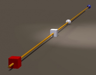
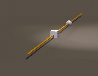
Hither = 1, Yon = 100 Hither = 10, Yon =20, near and far ends don’t show in preview. They do show in Firefly render.

This can have a surprising effect. When the camera is inside an object, but less than the hither distance away from the edge, you won’t notice it in the preview because the objects mesh is clipped out. But when you render, the camera is surrounded by the object and will catch no light. This gives the “my renders are black / white / … while I have the right image in preview” kind of complaints.

It sounds stupid: how can one land the camera inside an object? Well, my bets are that it will happen to you when you’re into animation. Smoothing the camera track will give you some blacked-out frames. Previewing the camera track through the Aux camera, and/or adding a ball object on top of the camera entry point (watch shadows!!) can help you to keep the view clear. Just setting the camera to Visible in the preview might not be enough.

Having said that, let’s have a look at the various camera properties.

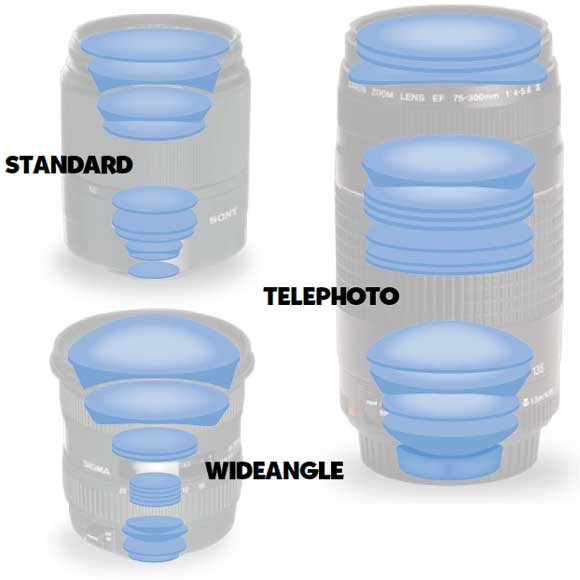
  • * Focal (length) refers to zooming
  • * Focal Distance and fStop refer to focal blur, and requires Depth of Field to be switched ON in the render settings.
  • * Shutter Open/Close refer to motion blur, which requires 3D Motion Blur to be switched ON in the render settings.
  • * Hither and Yon set limits in the openGL preview.
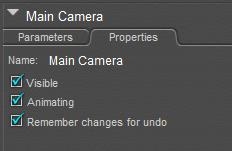
  • * Visible implies that I can see (and grab and move) the camera, when looking through another one. By default it’s ON.
  • * Animating implies that changes in position, focal length etc. are key framed. Great when following an object during animation, but annoying when I’m just trying to find a better camera position during an animation sequence. I tend to switch it OFF.
  • * And I can disable UNDO per camera. Well, fine.


Field of View

In order to determine the Field of View for a camera, I build a simple scene. Camera looking forward, and a row of colored pilons 1 mtr at the right of it, starting (red pylon) at 1 mtr forward. So this first pylon defined a FoV of 90°. The next pylon (green) was set another 1 mtr forward, and so on. Then I adjusted the focal length of the camera until that specific pylon was just at the edge of the image.

Pylon Color Focal(mm) FoV (°) Pylon Color Focal(mm) FoV (°)
1 Red 11 90,0 9 Blue 115 12,6
2 Green 24 53,1 10 Red 127 11,3
3 Blue 36 36,8 11 Green 140 10,3
4 Red 49 28,0 12 Blue 155 9,4
5 Green 62 22,5 13 Red 166 8,7
6 Blue 75 18,8 14 Green 178 8,1
7 Red 87 16,2 15 Blue 192 7,6
8 Green 101 14,2


For simple and fast estimates, note that (pylon nr) * 12,5 = Focal(mm), like 6 * 12.5 = 75, where (pylon nr) is (meters forward) at one meter aside. As an estimate. I can use this for further calculations, e.g. on the size of a suitable background image.

Example 1

I use a 35mm lens, which gives me a 36-40° FoV, and my resulting render measures 2000 pixels wide. Then a complete 360° panorama as a background would require 2000 * 360/36 = 20.000 pixels at least, and preferably 40.000 (2px texture on 1 px result). With a 24mm lens the preferred panorama would require 2* 2000 * 360/53.1 = 27,120 pixels.

Example 2

In a 2000 pixel wide render, I want to fill the entire background with a billboard-like object. For quality reasons, it should have a texture of 3000 (at least) to 4000 (preferably) pixels. When using a 35mm lens, every 3 mtr forward sets the edge of the billboard 1 mtr left, and the other edge 1 mtr right. Or: for every 3 mtr distance from the camera, the board should be 2 meters wide. At 60 mtrs distance, the board should be 40 mtrs wide, left to right, and covered with the 4000 pixel image.

Non-Automatic

Modern real life cameras do have various modes of Automatic. Given two out of

  • sensitivity (ISO, film speed),
  • diaphragm (fStop) and
  • shutter speed (open time)

the camera adjusts the third one to the actual lighting conditions, to ensure a proper photo exposure.

Some 3D render programs do something similar, like the Automatic Exposure function in Vue.

Poser however, does not offer such a thing and requires exposure adjustment in post. For instance by using a Levels (Histogram) adjustment in Photoshop, ensuring a compete use of the full dynamic range for the image. Poser – the Pro versions – on the other hand, support high end (HDR/EXR) image formats which can survive adjustments like that without loss of information and detail.

The Poser camera is aware of shutter speed, but it’s used for determining motion blur only and does not affect image exposure. The camera is also aware of diaphragm opening, but it’s used for determining focal blur only and again, it does not affect image exposure. The camera is not aware of anything like film sensitivity, or ISO. It’s not ware of specific film characteristics either (render engines like LuxRender and Octane are). With this respect, the Poser camera is limited as a virtual one.
Next >>

Managing Poser Scenes (04. Camera Lens Effects)

In real life, a camera consists of an advanced lens system, a diaphragm and shutter mechanism, and an image capturing backplane. The diaphragm (relates to focal blur of Depth of Field), and the shutter speed (relates to Motion Blur or 3D Blur) were discussed already, and the role of the backplane is played by the rendering engine (which will be discussed in other sections of these Missing Manuals).

Something to note when emulating realistic results, is the relationship between things, which is not looked after by Poser itself. Doubling the sensitivity, speed or ISO value of the backplane increases the visibility of noise / grain in the result, and for the same lighting levels in the result it also doubles the shutter speed (is: halves the net opening time), or reduces the diaphragm opening (or: increases the fStop with +1), or reduces the Exposure (in Poser: halves the value, in Vue: reduces with -1.00).

Hence, when I show pictures of a dark alley, people expect more motion blur (longer shutter time) and/or more grain. When I show a racing car or motor cycle at full speed, people expect a shallow depth of field, and grain too. And so on. Poser is not taking care of that. I have to adjust those camera settings and post processing steps myself.

The other way around, portraits and especially landscapes can do with longer exposure times, and will show nearly no grain in the image and hardly any focal blur (infinite depth of field). And most lenses have their ‘soft spot’ (sharpest result) at fS=5.6 (sometimes 4), by the way.

This leaves us with the lens system. In real life a physical thing, with some weight as well. Physical things have imperfections, and these will “add” to the result. Since the lens system sits between the scene and the image capturing backplane, those additions are added on top of the image. In other words, those imperfections can be added in post, on top of the render. Again, the imperfections are required to make a too perfect render look as being captured by a real camera, adding to the photorealism of the image. When you don’t want photorealism, don’t bother at all.

In the first place, the lens system is a tube and therefor it captures less light at the edges. This is called vignetting. A dark edge on the picture, very visible in old photographs. Modern systems on one hand have better, brighter lenses, and on the other hand the lenses are just a bit wider so the vignetting takes place outside the capturing area.

Vignetting is a must – like scratches – on vintage black and whites.

Second, the lens system consists of various glass elements. This introduces reflections, either within the element (scattering) or on the elements surfaces. The internal, scattering reflections blur the small bright areas of the image, known as glare. The external reflections generate the series of circles or rings, known as flare. The flare shapes can be pentagonal (5-sides), hexagonal (6-sides) or more to circular, this is determined by the shape of the diaphragm.

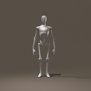
Glare, the light areas are glowing a bit

Flare, making rings around the bright spots

Flares always exist from a very bright light within the scene towards the middle of the image. The more elements are present in the system, the more reflections we’ll see. Note that fixed length lenses have far less elements than flexible zoom systems.

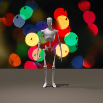
Another effect, called bokeh, appears when a very dark, blurred background contains small strong highlights. While they take the shape of the diaphragm (like flares) they scatter around in the lens system. Normally they would not be visible, but they are since they are quite strong and the background is dark and blurred. While flare usually occurs in shots with no focal blur (or: infinite depth of field, outer space is a typical example), bokeh requires the background blur due to depth of field / focal blur. In most cases there is an object of focus and interest in the foreground. So, one cannot have flare and bokeh in one shot.

Bokeh Star flare

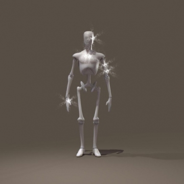
Third, the diaphragm itself can be the source of distortions: star flare. This usually happens when there are strong highlights in (partially) bright images, where the diaphragm is about closed due to a high fStop number. This tiny hole in the wall refracts light along its edges. A six-piece diaphragm will create a six-pointed star.

Note that the conditions for flare and star-flare contradict: flare needs an open diaphragm due to the dark background (like outer space) while star-flare requires a closed diaphragm due to the bright environment (sun on a winters day). The well-known sci-fi flares (Star Trek), having circular flares ending in a starry twinkle, are explicit fakes for that reason alone. One cannot have both in the same shot.

All these effects can be done in post, after the rendering. Sometimes you need Photoshop for it, perhaps with a special filter or plugin. Vue can do glare and both flares (but not bokeh) as part of the in-program post-rendering process.

Note: some people use flare as a container concept: everything that is causing artifacts due to light shining into the lens directly. Glare, flare, star-flare and bokeh are just varieties of flare to them. No problem, it’s just naming.

Next >>

Managing Poser Scenes (05. Camera Stereo Vision)

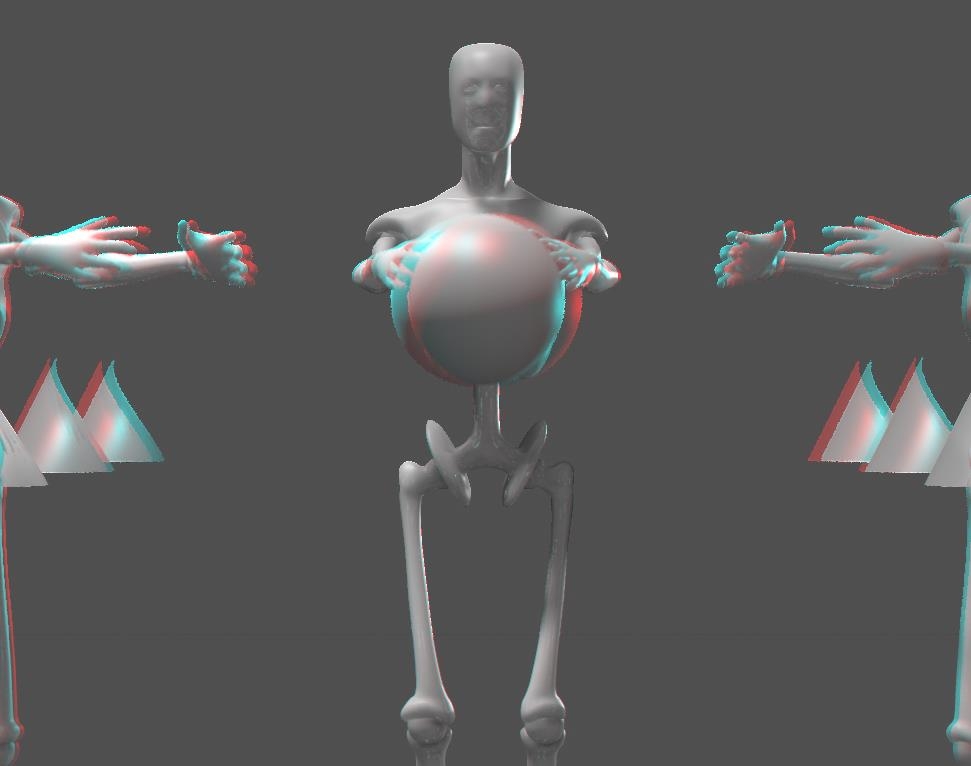
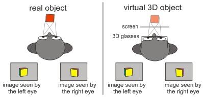
Once I manage to get images out of my 3D software like Poser or Vue, I might ask myself: “can I make 3D stereo images or animations as well, like they show on 3D TV or in cinema?” Yes I can, and I’ll show you the two main steps in that process.

Step #1 is: obtain proper left-eye and right-eye versions of the image or animation
Step #2 is: combine those into one final result, to be displayed and viewed by the appropriate hardware

Combining Left- en Right Images

In order to make more sense out of step 1, I’ll discuss step 2 first: how to combine the left- and right eye images.

Anaglyph Maker

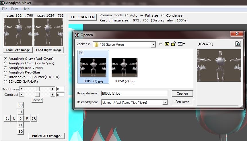
For still images, this can be done in a special program like the Anaglyph Maker, available as a freebee on the internet http://www.stereoeye.jp/index_e.html. It’s a Windows program. I unpack the zip and launch the program, there is nothing to install. Then I load the left and right images

And I select the kind of 3D image I want to make, matching my viewing hardware. The Red-Cyan glasses are most common, as Red and Cyan are opposite colors in the RGB computer color scheme. Red-Green however presents complementary colors for the human eye but causes some confusion as Magenta-Green are RGB opposites again. Red-Blue definitely is some legacy concept.

When I consider showing the result on a interleave-display with shutter-glasses, or a Polarization based projection scheme, Anaglyph Maker can produce images for those setups as well. Those schemes do require special displays but do not distort the colors in the image, while for instance the Red-Cyan glasses will present issues reproducing the Reds and Cyans of the image itself. This is why images in some cases are turned into B/W first, giving me the choice between either 2D color or 3D depth. Anaglyph Maker offers this as the first option: Gray.

I can increase Brightness and Contrast to compensate for the filtering of the imaging process and the viewing hardware, and after that I click [Make 3D Image].

Then I shift the left and right images relative to each other until the focal areas of both images coincide. The best way to do that is while wearing the Red-Cyan glasses, as I’ll get the best result immediately.

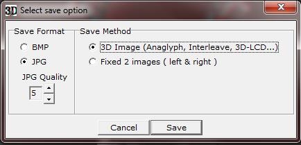
Now I can [Save 3D Image] which gives me the option of saving the Red-Cyan result

Or the (uncolored) left and right images, which are shifted into the correct relative positions.

Photoshop or GIMP or …

Instead of using special software, I can use my imaging software instead. For single stills this might be tedious but for handling video or animations it’s a must, as there is no Anaglyph Maker for handling all movie frames in one go, while Premiere or so are quite able to do that. And then I’ve got my own 3D stereo movie.

  1. 1. Open the Right-eye photo (or film)
  2. 2. Add a new layer on top of it, fill it with Red (255,0,0) and assign it the Screen blending mode
  3. 3. Open the Left photo (or film) on top of the previous one
  4. 4. Add a new layer, fill it with Cyan (0,255,255) and assign it the Screen blending mode
  5. 5. Merge both top layers (the Left + Cyan one) into one layer and assign this result the Multiply blending mode. Delete the original Left+Cyan layers, or at least make them invisible
  6. 6. Shift this Left/Cyan layer until the focal areas or the Right/Red and this Left/Cyan combi align
  7. 7. Crop the final result to lose separate Red/Cyan edges, and save the result as a single image.

Please do note that I found that images with transparency, like PNG’s, present quality issues while non-transparent ones (JPG’s, BMP’s) do not. Anaglyph Maker supports BMP and JPG only. I can swap Left and Right in the steps above, as long as the Right image is combined with a Red layer (both start with ‘R’, to easy remembering), as all Red-Cyan glasses have the Cyan part at the right to filter the correct way.

Obtaining Left-eye and Right-eye images

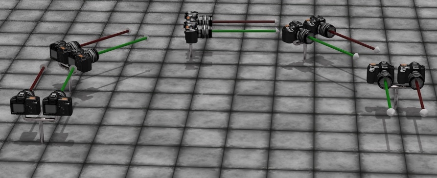
Although in real life dedicated stereo cameras can be obtained from the market, this is not the case for 3D software like Poser or Vue, so I’ve got to construct one myself. Actually I do need two identical cameras, a left-eye and a right-eye one, at some distance apart, fixed in a way they act like one.

(Image by Bagginsbill)

The best thing to do then is to use a third User Cam, being the parent of both, and use that as the main view finder and if possible, as the driver of the settings of both child cameras.

Such a rig guarantees that camera movements (focal length adjustments, and so on) are done in sync and are done the proper way. Like rotations, which should not take place around each individual camera pivot but around a pivot point common for both eye-cameras. In the meantime, the User Cam can be used for evaluating scene lighting, composition, framing the image and so one before anything stereo is attempted.

Les Bentley once published a Stereo Camera rig on Renderosity. You can download it from here as well, for your convenience. Please read it’s enclosed Readme before use.

Now I’ve grasped the basic principle, the question is: what are the proper settings for the mentioned camera rig? Is there a best distance between the cameras, and does it relate to focal length and depth of field values? The magic bullet to these questions is in Berkovich Formula:

SB = (1/f – 1/a) * L*N/(L-N) * ofd

This formula works for everything between long shot and macro take, is great for professional stereoscopists working in the movie industries, and helps them to sort out the best schemes for anything from IMAX cinema to 3D TV at home, or 3D gameplay on PC. It relates the distance between both cameras, aka the “Stereo Base” SB with various scene and camera settings:

  • * f – focal length of the camera lens (as in: 35mm)
  • * a – focal distance, between the camera and the “point of sharpness” in the scene (as in: 5 meters = 5000mm).
  • * L, N – refer to the nearest and farthest relevant objects in the scene, as in: 11 resp 2 meters. On the other hand, both can be derived from Depth of Field calculations, given focal distance and f-stop diaphragm value.
  • * ofd – on film deviation, as in: 1.2mm for 36mm film. What does it mean? When I superimpose the left- and right-eye shots on top of each other, and make the far objects overlap, then this ofd is the difference between those shots for the near objects. Or when I superimpose the shots on the sharp spot (as I’m expected to do in the final result), then this ofd is the deviations for the near- and far objects added together. This concept needs some translation to practical use in 3D rendered images though. I’ll discuss that later.

So for the presented values: SB = (1/35 – 1/5000) * 11*2/(11-2) * 1,2 = 0,083 meters = 8,3cm which coincides reasonably with the distance between the human eyes.

For everyday use in Poser or Vue, things can be simplified:

  • * the focal distance a will be much larger than the focal length f as we’re not doing macro shots, so 1/a can be ignored in the formula as it will come close to 0
  • * the farthest object is quite far away from the camera, so L/(L-N) can be ignored as it will come close to 1
  • * the ofd of 1.2mm for 36mm film actually means: when the ofd exceeds 1/30th of the image width we – human viewers – get disconnected from the stereo feeling, as the associated StereoBase differs too much from the distance between our own eyes.
  • * It’s more practical to use the focal distance instead of the distance to the nearest object, as focal distance is set explicitly for the camera when focusing.

As a result, to make the left and right eye images overlap at the focal point, one image has to be shifted with respect to the other, for

(Image shift) = (Image width) * (SB * f) / (A * 25)

With image shift and image width in pixels, StereoBase SB and focal distance A in similar units (both meters, or both feet), and focal length f in mm. For instance: with SB=10 cm = 0.1m, f=35mm and A=5 mtr a 1000 pixel wide image has to be shifted 1000 * 0.1 * 35 / (5 * 25) = 28 pixels.

For a still image, I do not need formulas or calculations as I can see the left and right images match while nudging one image aside gradually in Photoshop. But in animations, I would not like to set each frame separately. I would like to shift all frames of the left (or right) eye film for the same amount of pixels, even when focal length and focal distance are animated too. This can be accomplished by keeping SB * f / A for constant, by animating the StereoBase as well.

Next >>

Managing Poser Scenes (01. Intro)

Badly lit or rendered images are like vampires: they’d better stay out of the daylight.

Download this tutorial in PDF format (3.5 Mb).

Introduction

Working with Poser is like working in a virtual photographer’s studio. And in order to master the tools of the trade, I enter my empty virtual studio early in the morning, with no models or products to be shot around yet. This leaves me

In this series of tutorials, I’ll discuss them one by one.

Next >>