What’s the Blinn node used for?

Nodes are the essential building blocks in the Advanced interface to the Poser Material Room. They are the graphical representation of mathematical function calls, that is: calculation procedures which turn parameters (inputs) to a result (output).

Intermediate

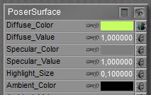
All nodes in the Specular group respond to specular light, which refers to specular light from direct (point- spot- infinite) sources only. The regular ‘specular’ node itself, either separate or embedded in the PoserSurface definition directly is fast to calculate, but falls short for a neat illusion of about any real stuff except hard plastic.

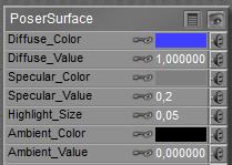
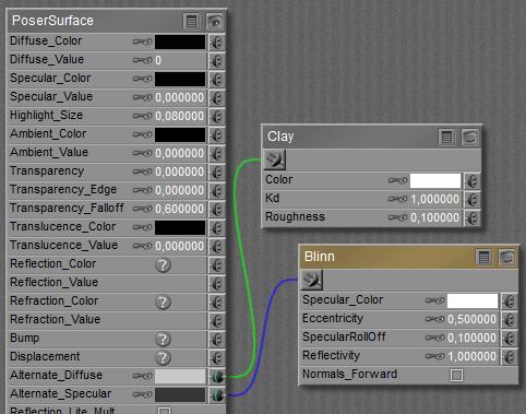
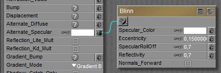
This is why Poser offers alternatives, like Blinn, or Anisotropic for microscopically grooved surfaces. Effectively Blinn relates to Specular as Clay relates to Diffuse: it’s the improved version for generic purposes. In other words: when I do need Clay (or other improvements, like Scatter) to represent surface roughness, then I do need Blinn for the according specularity. Just nullify or black out the regular Specular slot in PoserSurface, and plug the Lighting > Specular > Blinn node into Alternate_Specular.


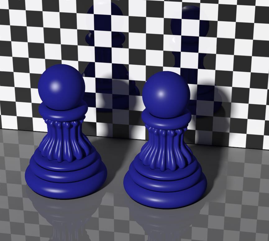
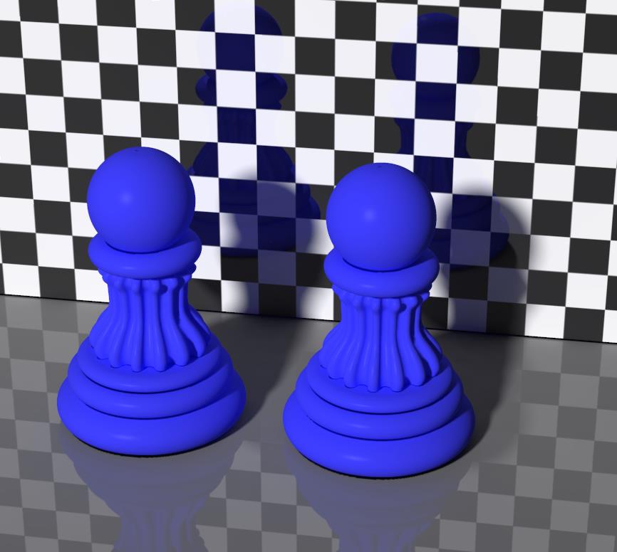
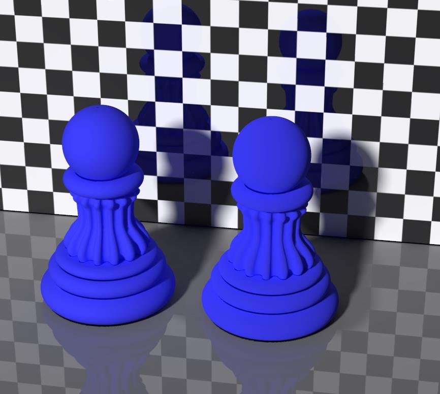
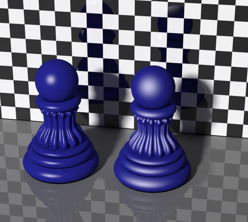
Above: the left pawn has regular specularity (highlight size 0.05) while the right pawn has Blinn. Parameters at 0.15 / 0.7 / 0.7 make a sort of matching specular strength, but note the strong center of the highlight in Blinn.


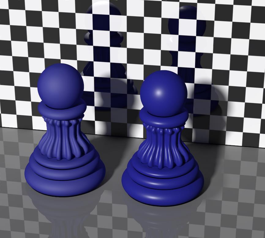
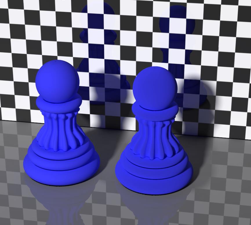
Above: the right pawn has parameters at 0.15 / 0.7 / 0.7 as before, now the left pawn at 0.5 / 0.1 / 1.0 representing a porous, soft, diffusing surface. There still is some resemblance of highlight, though. So the question is: what do the parameters mean, and how do they relate to regular specularity?

Well, Specular_Color and Normals_Forward are the same, while Reflectivity sort of matches Specular_Value. It serves the same purpose at least, though I need different values for a similar effect. When Eccentricity is low (< 0.1) the highlight is sharp like regular specular, and when it’s 0.2 or up the represented stuff looks mildly porous like the roughness of clay. Values will be quite different though, and differ from the regular Highlight_Size as well, so it’s a matter of experimenting what works best in my scene. The SpecularRollOff also affects the impression of porosity.

Next >

What’s the difference between the Specular component, and the Specular node?

Nodes are the essential building blocks in the Advanced interface to the Poser Material Room. They are the graphical representation of mathematical function calls, that is: calculation procedures which turn parameters (inputs) to a result (output).

Intermediate

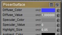
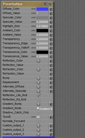
The Specular component in the PoserSurface material definition acts as a neutral entry into the spine with the specular node already attached to it. This embeds the material definition as represented by the specular node into the PoserSurface.
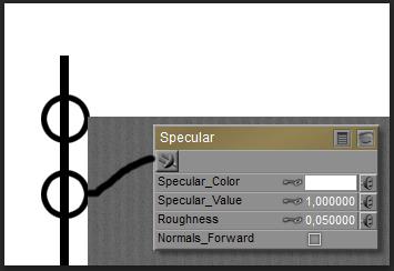
The specular node itself enables me to apply this definition explicitly in other occasions, like an element in a shading tree plugged into the Alternate Specular entry. So, when I disable (blacken out) the Specular component and plug the specular node into Alternate Specular (which is a neutral node by itself), I’ll get the same result.

On Specularity node parameters


Left: Specular Color, Value (set to 0.2), Highlight Size (0.05) and Normals Forward embedded in the PoserSurface definition. Right: the embedded diffuse is nullified (Value=0), the node is plugged into Alt Specular.

Like the PoserSurface component itself, the Specular node has Color, Value and Normals Forward for parameters. Highlight Size as used in the PoserSurface and Roughness as used in the node refer to the same, just different words for the same concept. The same value will render the same result. The smoother the surface, the smaller the roughness value, the sharper, stronger and smaller the highlight will be. Note however that Highlight Size and Roughness come with different default values.

Left: Highlight size 0.05, right: highlight size 0.25.

On highlights and specularity

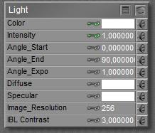
The Specular node (as well as its embedded variant, as well as all its alternatives) responds to specular light, which refers to specular light from direct (point- spot- infinite) sources only.
  <=>  

Nor IBL direct lights, nor IDL lighting setups do supply any specular lighting, and therefore cannot create highlights in the render.

Note that any form of specular lighting, handled by the specular nodes or any of its alternatives (Blinn, …) actually represents the reflection of the direct lights in the scene themselves onto the object surface. The reflective properties of a PoserSurface only bounce the (diffuse) light from surrounding objects in the scene, not from lights. As reflected light itself is considered diffuse and not specular, reflections of lights in mirrors, metal objects or anything else will not create highlights on other objects by themselves.

Also note – with respect to IDL and reflections – that the resulting highlights from specular lighting will be considered diffuse light themselves. So they will contribute in IDL lighting the scene, they will occur in reflections, and again – they will not create highlights on other objects.

So, the Specular node (as well as its embedded variant, as well as all its alternatives) responds to specular light. The response is to re-emit the received light, independent of any angle of incidence for the incoming light rays, in the form of highlights on the surface. Plus: Color and Value work together.

Variations

As Poser is not raytracing to derive the specular highlights and as blurred highlights are not properly described by the sharp “angle in equals angle out” concept as is the case with decent mirrors, one has to define another rule for re-distributing the bounced light. And though the specular principle calculates and renders pretty fast, it produces quite unrealistic results and makes everything look like a bad representation of hard plastic. This is why Poser offers alternatives, like Blinn or Anisotropic  for microscopically grooved surfaces.

A decent run-down on various specular reflection models is here: http://en.wikipedia.org/wiki/Specular_highlight

There is a confusing nomenclature in Poser regarding “Phong”. There is a Phong node, but it does not implement what is now called the Phong Reflection Model. It implements something that Mr. Phong used in the 70’s which has now been discarded because computers are so much faster – we can use better models. With some subtle differences and variation, we can make these connections:

  • The “Phong distribution” explained in that Wikipedia article is what in Poser is called the Specular node.
  • The “Ward anisotropic distribution” is our Anisotropic node.
  • The “Cook-Torrance model” is our Blinn node. (As far as I can tell, Blinn took the Cook-Torrance model and improved upon it – resulting in the Blinn-Phong reflection model. Or something like that.)

The Glossy node is none of these. It is a clever little cheat to deal with the fact that our CG lights are effectively point sources. A point light has no dimension, and a perfect glossy specular reflection of it would have no dimension, either. The Glossy node ignores that little fact. It simulates what you’d get from a glossy surface if the light actually had some finite width to it.

by Bagginsbill, Renderosity forum, 2009

Next >
What’s the Clay node used for?

Nodes are the essential building blocks in the Advanced interface to the Poser Material Room. They are the graphical representation of mathematical function calls, that is: calculation procedures which turn parameters (inputs) to a result (output).

Intermediate

The default Diffuse property of materials offers a reasonable representation for smooth, hard materials. But for materials of a more porous nature the Clay node is a far better alternative. Think of skin, cloth, wood and all other kinds of natural stuff, brick, stone, non-glazed pottery, rubberish soft plastics, etcetera. Note though that some materials, especially skin and soft plastics or rubbers, have got some advanced alternatives in recent Poser versions. These are the various ‘scatter’ nodes. As can be expected, such alternatives do require more parameters, and more render time.

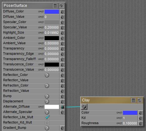
Anyway, like the Diffuse node the Clay node is meant to be plugged into the Alternate Diffuse slot (Advanced interface only), while having the Diffuse portion of the PoserSurface definition be zeroed out:


The Clay node offers Color and Kd for parameters which have the same meaning as Color and Value for Diffuse. The new kid on the block is: Roughness.

A low value makes the surface smooth, and the default 0.1 turns the Clay into a Diffuse equivalent. Lower values make no significant difference, but higher values (up to 1.0) do.

The scene above compares regular Diffuse (left) with Clay response (right) having Roughness set to 0.1. Specularity is at default value. I hardly see a difference: Diffuse is a special case of Clay.


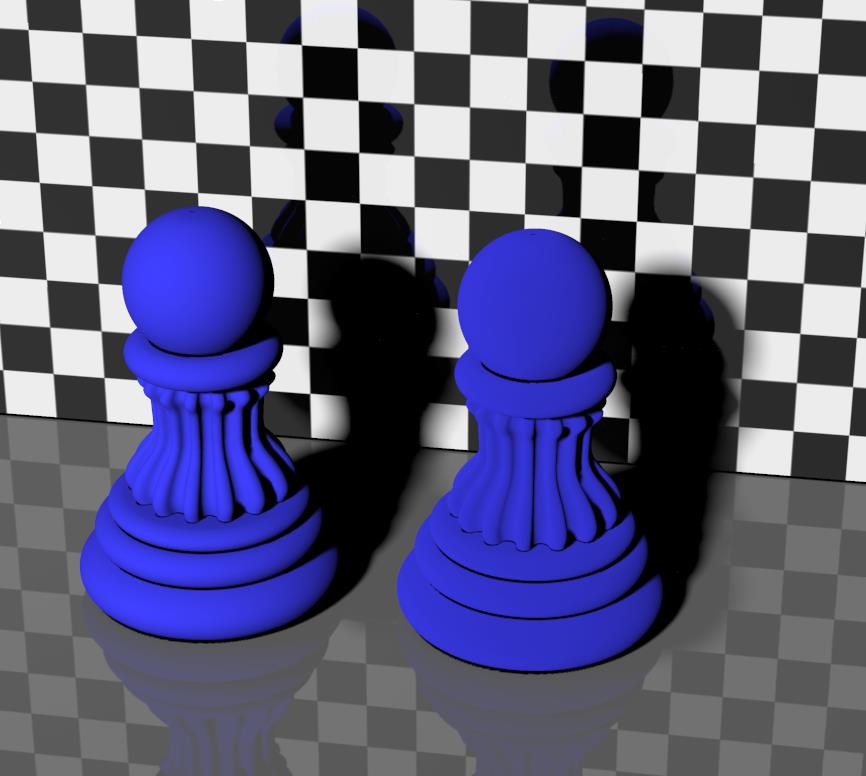
Both two scenes above have specularity turned OFF for demonstration purposes, and use the Clay node for diffuse response. Roughness is set to 0.1 (both left pawns, representing regular Diffuse) versus 0.5 (left image, right pawn) and versus 1.0 (right image, right pawn) respectively.

Maybe you’ve already noticed that the porous material, using the Clay node, re-emits less light in the forward direction (it’s slightly darker *) but experiences a reduced falloff near the edges (the higher the roughness, the less darkening at the sides reveal the shape of the object). The first is the result of the pores absorbing more light, the second is because the pores make the surface more irregular. The higher the Roughness, the more obvious this effect.

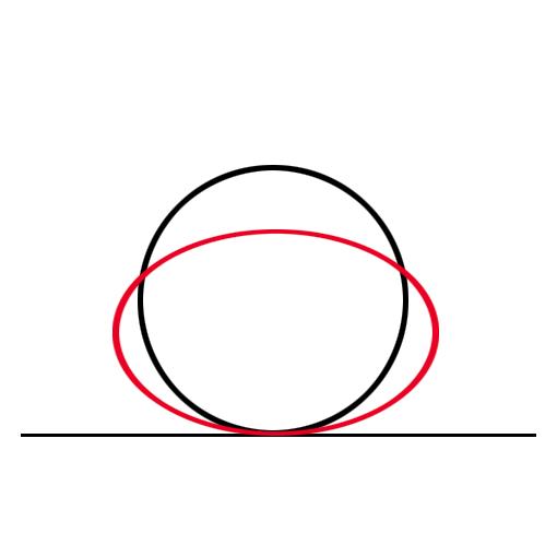
The graph shows this in another way. The black circle represents the light intensity from classic Lambert diffusion. Lots of light perpendicular from the surface, no light parallel to it, and a cosine fall-off for angles in between. The red curve represents the Clay effect: less light perpendicular compared to diffuse, but less intensity-falloff at the edges.
Surfaces with small pores (soft plastics, skin, plant leaves) will benefit from low roughness values, say 0.2 to 0.4 while surfaces with noticeable pores (brick, pottery) will benefit from larger values (0.7 to 0.9).

(*) since IDL light scenes will have the light coming from about all directions, the effect on light distribution – as being darker in the forward direction – will be less noticeable. Rendering with direct light only makes this Clay effect far stronger.


In the image above (with no specularity), the left pawn represents regular diffusion or clay with Roughness set to 0.1 while the right pawn represents clay with Roughness 1.0; just like the image before. But now, IDL lighting is OFF. Now the difference between them is much larger. This implies that when I render my scene under IDL conditions, it might become questionable whether it pays off to implement the clay node instead of regular diffuse.

Next >

What’s the difference between the Diffuse component, and the Diffuse node?

Nodes are the essential building blocks in the Advanced interface to the Poser Material Room. They are the graphical representation of mathematical function calls, that is: calculation procedures which turn parameters (inputs) to a result (output).

Intermediate

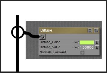
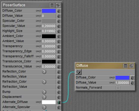
The Diffuse component in the PoserSurface material definition acts as a neutral entry into the spine with the diffuse node already attached to it. It embeds the material definition as represented by the diffuse node right into the PoserSurface.

is equivalent to

The separate diffuse node itself enables me to apply this definition explicitly in other occasions, like an element in a shading tree plugged into the Alternate Diffuse entry. So, when I disable (blacken out) the Diffuse component and plug the diffuse node into Alternate Diffuse (which is a neutral node by itself), I’ll get the same result.

The Diffuse node (as well as its embedded variant) responds to all sorts of diffuse light. When IDL lighting is enabled, this not only includes diffuse light from direct (point- spot- infinite) sources but also includes the ambient, reflected, diffused and specular-turned-into-highlight from surrounding objects in the scene. The response is to re-emit the received light, independent of any angle of incidence for the incoming light rays, according to Lamberts formula. Plus: Color and Value work together. This Lambert representation of material is fast to calculate, but falls short for a neat illusion of especially porous stuff like cloth, wood, plants, skin, brick, etc. Those materials might be better off with the Clay node. Additional alternatives are offered by the various Scatter nodes.

   <=> 
Left: Diffuse Color, Value (set to 1.0) and Normals Forward embedded in the PoserSurface definition. Right: the embedded diffuse is nullified (Value=0), the node is plugged into Alt Diffuse. Like in the PoserSurface itself, the Diffuse node has Color, Value and Normals Forward for parameters.

Next >

What are the Alternate Diffuse and Alternate Specular components intended for?

Those components of the PoserSurface material definition are available in the Advanced interface only. For short: their purpose is to offer alternatives for the regular Diffuse and Specular components. And although they are almost equivalent, do note one major difference between Alternate_Diffuse and Alternate_Specular: the first is affected by Transparency, the second is not. Just like regular Diffuse and Specular. When using (either of) them, do no forget to disable the regular Diffuse and/or Specular components. Just setting the Diffuse Value and/or Specular Value to 0.0 will do.

Intermediate

The PoserSurface material definition presents a regular Diffuse and Specular component, which are embedded equivalents of the diffuse and specular material tree nodes. Both nodes regulate the re-emission of received (diffuse resp specular) light, and have a basic angular distribution for that build into them. See the Lambert method, build into Diffuse.

Although materials represented this way do fine in case of hard plastics, they’re not doing very well in case of other – more organic – materials. Therefore other nodes are offered, like clay (the usual substitute for diffuse) and Blinn (one of the regular alternatives for specular). These nodes need a ‘neutral’ slot on the PoserSurface spine to be plugged in, and both Alternate ones offer that.

Since both slots are just neutral (*) entries to the PoserSurface spine, I’m free to plug the clay node into Alternate Specular, or to plug the Blinn node into Alternate Diffuse although the suggestion is to do otherwise for the sake of readability, understandability and maintainability of the surface definition. I can use the diffuse and/or specular nodes to bring the “good old” angular distributions back into the game, and I can use the “add” nodes to combine diffuse, specular and eventually also ambient, bump, reflection, refraction and other components to build my own equivalent of the PoserSurface spine, and then plug its result into Alternate Diffuse only. Some material-defining tools (e.g. Bagginsbills’ MatMagic, SnarlyGribblys’ EZMat ) work about that way. Transparency however can’t be dealt with that way, there is no substituting node for it either.
Nevertheless, the main intention is: disable the regular Diffuse and/or Specular entries, and plug the intended alternatives into the appropriate Alternate entries to get a more realistic material definition.

(*) when nothing is plugged in, the slot will not contribute to the PoserSurface definition in any way. When something is plugged in, the slot offers an additional color filter, and delivers the (filtered) color result into the PoserSurface definition. In there, it gets added up on a color-by-color basis. This means that I might have to pay attention to overlighting conditions.

The various nodes plugged into the Alternate slots have to pick up the lighting from the scene themselves. See node-tree building on this.

Next >

What’s the Translucence component intended for?

The Translucence component in the PoserSurface material definition is the complete equivalent of the Ambient component, except that Translucence is available through the Advanced interface only and in various cases is not exported or translated to external renderers or materials definitions, while Ambient is available in the Simple and Advanced interfaces and in far more cases is exported or translated decently to external renderers or material definitions. So for those reasons, Ambient is preferred by most people.

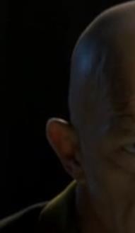
Why having Translucence then? Well, it’s a kind of service for those who want to separate real-life object glow as it appears by led-lights of phosphorescence from faking real-life translucency (as it appears in wax candles, human skin and rice paper walls) by some sort of body glow. They can put the first effect in Ambient, and the second in Translucence. This second effect becomes obsolete though for those who use the real thing instead: sub-surface scattering as recently build into Poser.


human skin translucency, light scattering through ear tissue.

Next >

What’s the Refraction component intended for?

What refraction is about…

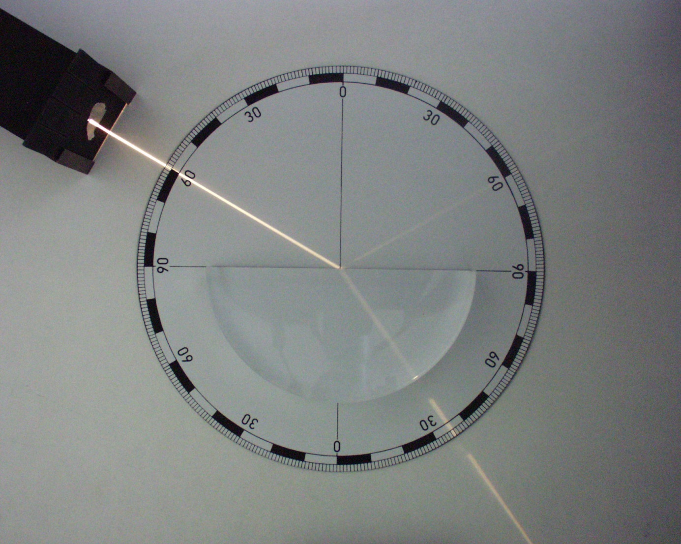
When light passes a transparent material like glass or fluid, or more precise: passes a surface with different transparent materials on both sides (air/water, air/glass, water/glass, … ), it bends.

The angle depends on the physical properties of the material defined as Index of Refraction (IoR, see this article on values). Then denser the material, the higher the value. The light bends towards the surface normal pointing towards the denser material, so from air to glass: inward, en from glass to air: outward. For a block of glass this means that the light coming out moves parallel to the light coming in, the block just shifts the scene behind the block somewhat aside.

What Poser is about…

The refraction component as such does not do anything specific. It takes any node construction plugged into it, filters it with a color and a value, and adds it to the PoserSurface set of material definitions. So I can put in an image_map, but in contrast to reflections that’s not done often as the refraction needs to represent the scene behind the object, with shifts and bends according to the object shape and thickness. A proper image would be tough to construct.

The node supposed to be connected to it is Refract, from the Lighting group. Note that although refraction mimics a full transparency of the object, the object itself remains opaque for direct lighting, and refraction is not reduced when transparency itself enters the stage as Poser Transparency affects Diffuse and Alternate_Diffuse only. One can reduce the Refraction_Value (or dim the Refraction_Color) accordingly, but the transparency from refraction, and transparency from PoserSurface are still different things.

Combining Transparency, Reflection, Refraction and Gamma Correction (from Render Settings) in one mix might seem a logical thing to do, but will raise numerous issues.

  • Combining Transparency and Reflection causes long render times due to infinite internal reflections within the object;
  • Balancing Reflection and Refraction requires fine instruments like Fresnel;
  • Transparency and Refraction are sort of duplicating each other and
  • The Gamma mechanism is well-known for distorting established balances between components.

In various articles you can find more on the refract node, on the Fresnel node, on combining Transparency and Raytracing, and on Gamma Correction (principles and advanced) itself. It might make your brain twist.

Next >

What are the Custom_outputs intended for?

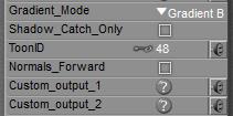
Like the ToonID, checking the Custom 1, 2 and/or 3 Auxiliary render data options in Render Settings enables extra layers in the export of the render result in Photoshop PSD format. This PSD layered export is available in Poser Pro only, and so are the three Custom fields.

When no additional actions are taken,

  • Custom 1 represents Diffuse
  • Custom 2 represents Specular
  • Custom 3 represents Shadow

When in doubt about the meaning of C1, C2 and C3, the Dimension 3D script for Render FireFly (in the Scripts > Partners menu) can help me out.

But I can take additional actions, and plug in any node tree into any of the Custom slots in which case that node tree takes over from the default meaning. It won’t affect the render result at all, as the extra PSD layers are meant for supporting post processing only (masks, selections, …).

Establishing the extra info might affect render time and memory use of course and it will generate the content as I require into the appropriate PSD-layers, once I take that format for exporting the render result.

Next >

What’s the ToonID intended for?

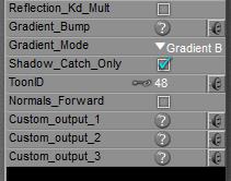
Each PoserSurface has a ToonID value assigned, and one can even make it varying over time (animated) as well as driven by a node construction, like a complex of math_functions and variables like the frame_number.
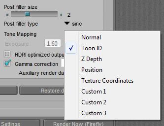
Various surfaces can get the same ID, when that helps me out. An instance of the render result, not showing colors and shades but showing ToonID’s instead, can be derived as follows:

  • In Render Settings, check the appropriate options in Auxiliary render data
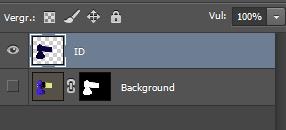
  • After rendering, export the image as a Photoshop PSD file. This file will present an “ID” Layer in which each Toon ID has a color of its own. This way the surface-areas can be selected easily for further modification in Photoshop (or alike).

Poser Aux render data and PSD layered export is available in Poser Pro only.

Next >

What’s the Shadow Catch Only intended for?

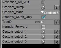
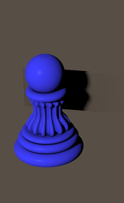
By switching ON the Shadow Catch Only option in a PoserSurface definition the surface will disappear completely, except from the shadows cast from other objects, and from itself as well.
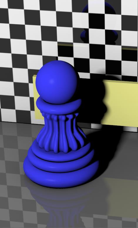
Generally, this feature is used to create a render that blends well onto another image with objects around, and this is a way to transfer the shadows from objects in the Poser scene to the other objects in the background layer. The background objects are recreated in the Poser scene for their shape only (primitives do fine jobs in most cases, like blocks for buildings)

=>

As the ‘real’ objects catching the shadows are in the background image, one should avoid having any objects behind (or visible through) those shadow catchers in the Poser scene. That’s why the back wall and ground plane were made invisible in the right image. Otherwise, these will hamper the blending of the render with the background, and catch shadows as well.

Next >