How does Poser handle my images for texturing?

For rendering purposes, Poser internally works with 16-bits-per color (High Definition) inputs and results. For display and for most image exports or the render result, a translation is made to the (Low Definition, 8-bits-per-color) image formats like JPG, PNG, etc. In Poser Pro, export to a High Definition format (HDR, EXR) is possible.

For input, most images will be in Low Definition format as well, usually JPG from photographs. These are fine for preview, but for rendering they are translated first to EXR format, and saved at a temporary place

(Poser Temp Folder)\PoserTextureCache

where the Poser Temp Folder is set in the Edit > General Preferences menu, Misc Tab

More handling details are managed through the Render tab in General Preferences

After an image is assigned, or when a material with image references is assigned to a surface or an object is loaded with such material definitions, the translation from Low to High Definition is made as a first pass of the render process. Unless I have the Run in Background Thread option checked (it’s ON by default), then Poser saves me the waits and utilizes spare CPU capacity when available.

The Texture Cache is filled up while building the scene and rendering, and cleared when Poser exits (in a regular way). Except for the <so many> MB’s of most recently added images. This way, some translation is avoided when I reopen Poser to continue my work on the same scene. This Persistent Size can be set as well.

Note that an EXR file requires about 7 bytes per pixel, which is 5 to 10 times as large as the JPG’s they originate from. So a single hires (4000×4000) image as used for most character skins takes about 100MB disk space. This space requirement is something to keep in mind when setting Persistent Size, and of course all the required space for keeping all images from my entire scene needs to be available when the rendering process kicks in.

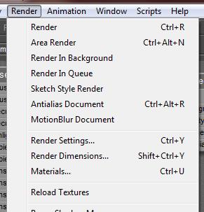
When an image is already translated into the Texture Cache, and then is modified in Photoshop or alike, such a modification will go undetected by Poser and the stack of available EXR files need to be refreshed. I have to do so manually, using the Render > Reload Textures menu.

You might be interested in the other article, on handling movie files.

Next >

How can I assign an image to a material?

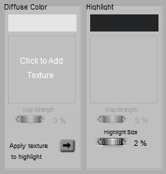
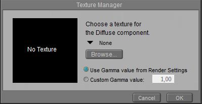
Assigning an (external) image to a material is quite a common action, whether it’s for light gels, background, or object surfaces. In Material Room, the Simple interface requires one click to open the Texture Manager window

=>

which lets me pick an image file (many formats supported) and (for Poser 10 / Pro 2010 and up) a Gamma value. As a rule of thumb:

  • When the component represents some kind of light towards the camera, which has to be added up to the light from other components, then the first (default) option is the right one. Think: (Alternate_)Diffuse, (Alternate_)Specular, Ambient and Translucence, Reflection and Refraction.
  • When the image represents just an amount of something and color is far from relevant (think: Bump/Displacement, Transparency, Highlight Size, …), then the second option should be selected with 1.0 as the right value.

Just a brief explanation for this: Gamma Correction, darkens the image before it’s applied and brightens the final render result for compensation. This brightens up the shadows to mimic the effects of radiosity from floors, walls , ceilings and the like, and from the scattering of light in a real, somewhat dusty atmosphere; effects which are hardly available in a Poser render. This Gamma mechanism also reduces the (risk of) overlighting when multiple sources of light (diffuse, specular, reflection, …) from a surface towards the camera are combined. Poser just adds them up and clips at 100%, while in real life our eyes adjust to the increased light levels.

But for the greyscale image-driven amounts, the render consequences suffer from the distortion: reduced displacements for instance cannot be compensated for in the final brightening pass. So, for these effects, the Gamma Correction has to be disabled by overriding the default value with a neutral 1.0.

Image management

When I already have various images in my scene, and when I do not want to recheck and reset all of them, Poser can help me with various scripts:


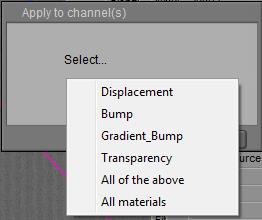
This leads me to …

where “All of the above” is the recommended option.

Note that images driving Edge_Blend and nodes alike have to be dealt with manually; these also should have their Gamma value set to 1.0.


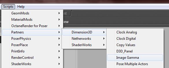
And also (Poser 10 / Pro 2014 and up):

which presents:

Warning: when a single image file is referred to in multiple places, for multiple material definition components, and/or for various objects, then the image is imported and handled into Poser only ONCE. It’s this single instance which gets a Gamma value assigned, whatever way I choose. Changing the value at one place alters it in all other places, for that image.

Intermediate

In the Advanced interface to the Poser Material Room, nodes are the essential building blocks. They are the graphical representation of mathematical function calls, calculation procedures turning parameters (inputs) to a result (output).

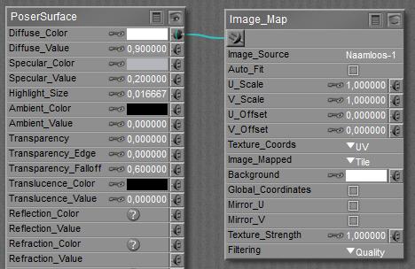
For applying images, the Image_map node can be found in the 2D Textures group, and reads like …

Clicking Image_Source opens the Texture Manager as discussed above, and enables me to assign an image file and a Gamma value. As said, addressing the same file in multiple nodes will still associate ONE gamma value to that value. When I use various values in the nodes, then the last one entered is the final value for all of them.

The next set of parameters (U/V_Scale, U/V_Offset, Texture_Coords, Image_Mapped plus the Global_Coordinates checkbox) all affect the mapping of the image onto the object surface. Just consult the manual for the meaning of the various options. Checking Global_Coordinates is meaningful in combination with the XY, XZ, YZ options of Texture_Coords, while the Mirror_U/V options are meaningful in combination with the Tile option from Image_Mapped: the images is tiled and the tiles are flipped successively.

For all places where no image pixel is available (due to the mapping parameters), the Background will be used instead. When Image_Mapped is set to Alpha then any transparency information from the image itself is used for this too, and Background might fill in some spots within the textured area as well.

Texture Strength works as follows: say the image map is connected to a color-swatch in PoserSurface. Then first the image is merged with white: Strength 100% means full image, 0% means no image at all. Second the result is filtered by the color-swatch, as usual. In other words, for an 80% Texture Strength, the final result consists of 80% color-filtered image, and for the remaining 20% of the color from the swatch itself.

Filtering comes into play at render time, when (usually) multiple pixels from the images become associated with a single pixel in the render result, especially when the rendering uses anti-aliasing itself (that’s Pixel Samples in the Render Settings). Or the other way around, and a single pixel in the image is used to fill multiple pixels in the result. Just that image pixel can be used (‘None’ for filtering) or info from its direct neighbors can be used as well (‘Fast’). The latter is fine for test renders, and for small sized animations for the web (say 640×480, regular YouTube). Looking one step further (‘Quality’) is the default, and recommended for larger animations (HD, DVD quality) and still images for the web. Looking another step further (‘Crisp’) takes even more pixels from the image into consideration, and might be of use for large scale, print-oriented render results. As usual, the higher the setting, the more memory and render time are required to finish the process.

Next >

What’s the Environment Map > Spherical Map node used for?

Nodes are the essential building blocks in the Advanced interface to the Poser Material Room. They are the graphical representation of mathematical function calls, that is: calculation procedures which turn parameters (inputs) to a result (output).

Intermediate

In order to show some kind of reflections in the render, the scene needs an environment to reflect. This might require the build of a complete scene behind the camera, which won’t show except for its reflections. As this can be quite tedious and far from cost-effective, one can use image maps instead. For just mimicking blurred reflections of far-away objects, skies and landscapes any simple projection (mapping) of an appropriate image onto the reflection component will do. This however should be considered unsatisfactory when either sharper reflection has to be considered.

Now, say, my scene is under a sky dome and on a ground floor, and an image is mapped to these environmental objects. In the scene, a single fully reflective object is present. Then: how would the dome and ground be reflected from that object (assuming there are no other things around to reflect)? Rendering full, crisp raytraced reflections from a complex shaped object can be time consuming.

This is when applying a “spherical environmental reflection map” becomes useful. Just plug the Sphere Map (the only node in the Lighting > Environment Map group) into the PoserSurface Reflection_Color (or Alternate_Diffuse) slot, and the image that might have been used for the sky dome into the Sphere-map Color slot. Now I’ll see the same reflections, but I don’t need the dome, and neither I need any raytracing for the reflections.

I might want to Color filter the image though, and I might want to Rotate it to match any sky dome actually used.

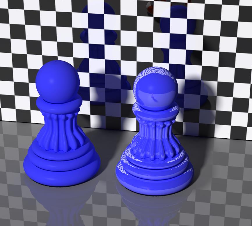
Now, is this any different from a regular mapping of the image around the object? Sure it is, have a look at this:

The right pawn has the tiling image mapped onto the object surface, in the Reflection or (alternate) diffuse component of the PoserSurface. The left pawn shows environmental spherical mapping, and looks like a mess at first sight. Unless I realize that the tiling image is mapped onto a (virtual) sky dome surrounding the scene, like the way the tiles are mapped onto the head ball of the right pawn. The ‘converging point’ where the tiles come together is not on the object itself, but somewhere straight above all objects, high in the sky.

Then such a colored sky dome is reflected by the left pawn, towards the camera. And that is what the spherical mapped texture is showing, in a correct way. Where image mapping usually either depends on the shape of the object (UV mapping) or the position of the object in the scene (XYZ mapping), this Environmental Spherical Reflection Mapping depends on the position of the object under the dome, relative to the camera. When either the object moves, or the camera moves (or both), the mapping will get adjusted.

Do we need it?

The obvious advantage is render speed, the obvious disadvantage is: it does not reflect any objects in the scene, let alone portions of the same object, since these are not in the image used. So, for stills of filled scenes rendered on modern, fast PC’s deploying IDL illumination and other raytracing demanding approaches, the use of the regular Reflect (or even Fresnel) node might be a better way.

But for those “shiny car on an empty road” advert-like animations, deploying this environmental spherical reflection mapping might be a game winner. And it might serve well in test runs too.

Next >

How do I properly combine Transparency and Raytracing?

Raytracing nodes like reflection, refraction and Fresnel work well for fully non-transparent surfaces. Refraction and Fresnel bring in full transparency on their own. As a consequence, those materials behave opaque to direct lighting, and produce dark shadows and block specularity as well. I might not want that.

Throwing in transparency however does have serious pitfalls, especially when combined with raytracing. Pitfalls and some ways to climb out of them are discussed here. Before doing so, it’s worthwhile pointing out that in Poser, transparency might mean:

  • Lace-like transparency. The surface has holes where the light shines through completely, and opaque areas with full diffuse, specular, reflective etc. properties. This kind of transparency is not discussed here, just set Poser transparency to 1 and use image maps to define the present and absent areas of the surface; then all will be fine.
  • Surface transparency. Imagine the object made of clear glass covered with a layer that absorbs light to a limited extend. This is what Poser has in mind when the material transparency value is reduced. 90% means that 10% of the light is blocked by that surface layer, so 90% x 90% = 81% of the light will pass the object (first object in, then out).
  • Volume transparency, the object is made from non-clear glass and light is dimmed and colored when it passes through, making the final result depend on object thickness and shape as well. This is not what Poser has in mind but one can mimic the dimming effect, for instance by translating an object transparency of 81% to a Poser surface transparency value of 90%. That assumes that the object has equal thickness all over. And when that’s not the case, Poser offers Transparency_Edge and Transparency_Falloff to mimic the effects of that.

Advanced

Transparency and Reflection

Poser raytracing does a fine and efficient job, when the scene presents a limited amount of bounces between objects. Parallel mirrors, fields loaded with mutually reflecting Christmas balls and more like that might either take large amounts of render time, or might produce artefacts when the rays are killed too early.

Exactly that happens when an object becomes both transparent and reflective. Light passes the object at the front, bounces at the back, bounces at the front and so on resulting in an infinite amount of internal reflections. This can prolong render times considerably, while reducing those with low(er) values of Raytrace Bounces in Render Settings might cripple the results somewhat. This means that I’ve got a challenge in finding the proper balance between time and quality.

Because light not only bounces from the surface at the first hit, but also gets light added from the bounces following on that, the final brightness of the reflection increases. This is according to real life, but unfortunately the dimming of the light during those internal bounces is not. Transparency in Poser is a surface effect, while it’s something volumetric in nature. The thicker the object, or the more bounces have taken place, the more light is absorbed on the way and the more the light is dimmed.

In math:

  • the Poser surface has a transparency T, which means that each time a ray hits the surface, that percentage of the light (say T=30%) will pass through. Then only 1-T (say 1-30% = 70%) remains for initial reflection, and reflectivity R can’t get larger than that. So if the surface is covered with a thin metallic foil which lets 30% of the light pass through, and that metal has a reflectivity by itself of 80%, then the surface will reflect 70% x 80% = 56% of the light initially. Sounds simple, but I have to adjust the reflectivity from 80% down to 56% to cater for the transparency, as Poser is not doing that when I use the Reflection component I in PoserSurface. Plugging the Reflect nod into Alternate_Diffuse however handles this for me, as (only!) Diffuse and Alternate_Diffuse are affected by the Transparency setting. In that case, I can simply use the 80% reflectivity as well.
  • Due to the internal reflections, the amount of light that will come out at the front, the final reflection, will be R (1+ T2/(1- R2)) like 0.56 * (1+ 0.32/(1-0.562)) = 0.633 which is a serious increase over the initial 0.56. This implies that there are no simple relationships between lighting levels measured in real life, and the Transparency settings for Poser.
  • In real life, the output would have been R (1+ T2/(1-(RT)2)) like 0.56*(1+0,32/(1-(0.56*0.3)2)) = 0.611 which is slightly less. So despite the large render time due to internal reflections, Poser is not doing so bad at all, the difference between the volume-model and the surface-model is something I can live with. Or I could just use a slightly less reflectivity instead (55% instead of 56% might do).

Note: Poser, from version 10 up and in all Pro versions, offers a Gamma Correction mechanism to enhance the photorealism of render results. Very recommended. As reflected light is considered an independent component in the surface definitions, the gamma mechanism should be applied to the Reflect settings. That is: all Values should remain at 1.0 (or 0.0, but no intermediate values), any reduction or coloring in reflectivity should be embedded in color swatches, and any image map involved should have set its Gamma set to Render Gamma or alike. However, Transparency itself is considered a ‘blender’: more of one component (say foreground reflecting) implies less of the other (background shining through). For those elements, the Gamma mechanism should be avoided or bypassed whenever possible. That is: Color swatches should remain white (or black), all intermediate values should be in a Value slot, and any images involved should have their Gamma value set to 1.0 if applicable. See this article for details.

Transparency and Refraction

All raytracing, including the Refraction node does work on indirect light from objects only. Direct light, whether diffuse or specular, is not reflected nor refracted. Such light, passing a refractive object, makes deep shadows and can’t make any highlights behind the object anymore. When I want the proper bright shadows of transparent objects, I need to use Transparency instead.

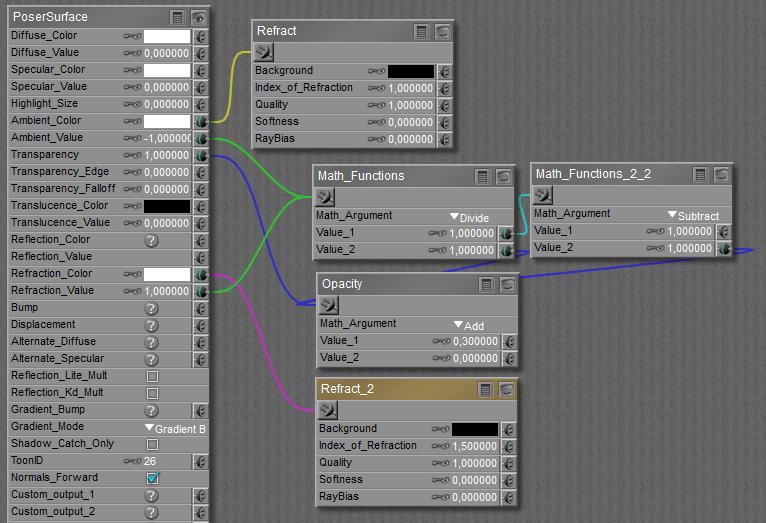
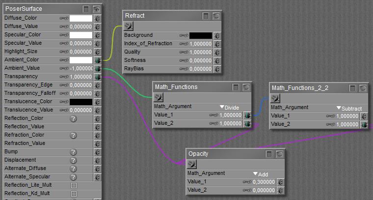
But now the scene behind the object will shine through twice: once due to transparency and one due to refraction, while I want the latter only since glasseous objects and liquids to refract (bend and shift the scene behind the object), while transparency does not. So I have to take the Indirect Light portion out of the Transparency, and this is the way to do it:

By using an IoR of 1.0 refraction is transparent only, no bending involved, and applies to indirect light only. The transparency itself applies to direct and indirect light, and so the subtraction results in the direct light portion only. The amount of refraction to be used here is proportional to the amount of transparency, but unfortunately the transparency slot turns into Opacity the moment a node gets plugged in. Then, black or low values make transparent and the value 0.3 shown above indicates a 70% transparency.

Now I can add in the required refraction (additional Refract node), with an IoR related to the material at hand, say 1.5. Again, the refraction is proportional to the amount of transparency so I can re-use that function outcome:

Transparency and Fresnel

In real life, at skew angles it gets harder for light waves to enter a material. So transparency decreases, and since the energy has to go somewhere, reflectivity increases. This is understood as the Fresnel principle.

The Fresnel node itself, or any simple combination of refraction with Fresnel_Blend, has the same (dis)advantages as a straightforward refraction: it assumes a full transparent clear object, which then behaves as opaque for direct light and produces far too hard shadows. So I’ll elaborate on the previous way of work instead.

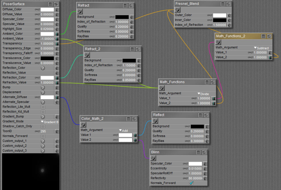
First, the fixed value for opacity can be replaced by a Fresnel_Blend node. This node has to represent opacity too, and so it has to produce high (white) values at skew angles and low (black) ones at the inside of the object.

Second, I add Reflect, and I’ll do so in the Alternate_Diffuse slot which gets adjusted for transparency automatically (like regular Diffuse).And since reflection caters for indirect light only I’ll add its equivalent for direct light: specular. In which case the Blinn node provides the best way forward.

So now I’ve got the definition for homogeneous glass or a liquid, uncolored but with a limited transparency, as presented by Bagginsbill (Renderosity forum, March 20, 2014):

For colored glass or liquid, the Refraction_Color can be adjusted. No other swatches need adjustment, as reflection and specularity go uncolored (except for metals, which are non-transparent) and Transparency goes uncolored as well, so the first Refract (added into Ambient) for compensation should stay uncolored as well: Ambient_Color remains white.

Next >

What’s the Raytrace > Fresnel node used for?

Nodes are the essential building blocks in the Advanced interface to the Poser Material Room. They are the graphical representation of mathematical function calls, that is: calculation procedures which turn parameters (inputs) to a result (output).

Intermediate

Fresnel is the elaborated combination of reflection with refraction (transparency included), as shown in nature by transparent materials like glass and liquid. Those materials show low reflection and high transparency at angles perpendicular to the surface, towards the camera, and high reflection and low transparency at skew angles towards the camera. The higher the (Index of) Refraction of the material, the stronger this effect. On the other hand: the less reflective a material, the more noticeable the effect as an object will become completely reflective at the edges, whatever its IOR.

Reflection makes light rays bounce from an object surface, to show scene elements between the object and the camera, and behind the camera as well. Transparency makes light rays pass through the object surface, showing scene elements behind the object (from the cameras point of view). Refraction then makes those latter light rays bend when passing the surface, and color them too.  Do note however that refraction brings its own transparency, and like refraction and reflection, Fresnel is supposed to work with fully non-transparent surfaces. If not, numerous issues have to be dealt with to get any believable result within feasible render times.

The Fresnel effect itself is supported by the Fresnel node (discussed here) and the Fresnel_Blend node. Like Refraction, Fresnel does require raytracing to be switched ON in Render Settings. The quality of the result depends on the ‘Number of Bounces’ set in Render Settings as well. This number is a maximum value, when Poser does not need them it won’t use them, but if the number of bounces for a light ray exceeds this limit, this light ray is killed. This might speed up the rendering while it also might introduce artifacts (black spots) in the result. The tradeoff is mine, but as nature has an infinite number of bounces, the max value is the best when I can afford it.

Do note that Fresnel – like Refraction – only handles the light from objects in the surrounding scene. It does not cater for the rays from direct light sources (spot, point, etc. lights), these will not get bend at all. Fresnel does not let light pass through an object shining onto another object, the object will be opaque for direct light, and shadows will be dark as a result. But Transparency behaves as expected, as described elsewhere in a basic and advanced way.


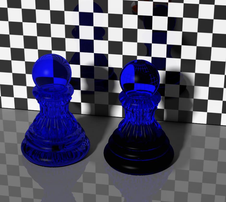
The right pawn still shows refraction as before, the left pawn shows Fresnel. Especially the upper edge of the left pawn clearly shows that Fresnel is not only transmitting the wall at its back, but also is reflecting it. These reflections are missing on the right pawn.

About the Fresnel node parameters:

The Index Of Refraction is mentioned above. Values for various materials can be found here.

Quality offers a tradeoff between speed and result; high values require longer render times but present crispier results. Softness increases the blur of the refracted image, representing irregularities, impurities and even minor movements and vibrations in the refracting surface.

Background is meant to fill in the pixels where no scene elements are around to be reflected, but it should be used with care because this idea is pretty meaningless for transparency / refraction. Otherwise I’m looking through a transparent surface, seeing things which are not there at all.

Refraction Color (in the PoserSurface column) gives color to the material, like red to wine or sapphire. But do note that this is a surface effect only, like a colored plastic cover around the object. Poser cannot do volumetrics, the wine will be equally red whatever way I look at it, and glass will be equally red whatever the thickness.

The final amount of refraction will be made up from the combination of Refraction_Color * Refraction_Value. This holds for the surface color as well as for the refractive and reflective effects themselves. To represent a dark colored material, I can either use a dark color in the swatch, or a low value. The Color will be affected by Gamma Correction, the Value will not so 80% White and 100% Value will behave different from 100% White and 80% Value under GC render conditions.

Rendering

Although reflection and refraction themselves do have another parameter, RayBias, in common, that one is missing here. This RayBias is introduced to avoid undesired optical effects from tiny surface irregularities, induced by displacement maps. Think of scars etc. on skin. Using RayBias speeds up the rendering but might introduce artifacts when set too high. So… Fresnel is more accurate at the tiny surface details, will not have the artifacts, but certainly will suffer from low render speeds when applied to a displacement-mapped surface.

Raytraced refractions and reflections are (sort of) realistic, detailed, and therefore time and resource consuming at render time. As a consequence, one should be careful not to put too many raytracing intensive challenges into one scene, otherwise the rendering will take forever. InDirect Lighting (IDL) is such a challenge, Fresnel – combining reflection and refraction is such a challenge, having a lot of reflective and/or refractive surfaces in one scene is a challenge, having reflections, refraction (and especially Fresnel) on a complex surface is a challenge, and having Max Bounces (and the IDL Quality options) set high in Render Settings make a challenge as well.

Take the Refraction vs Fresnel image shown above. It’s IDL, and reflective wall and floor, and quite high values in Render Settings. Rendering took 3.5 hours on quite a fast PC. Poser does have its limitations.

On top of all those things, raytracing is designed to work with a completely non-transparent surface; refraction caters for (full) transparency on its own. While doing so, raytracing works for objects in the scene only, it cannot handle direct light, nor the shadows or specularity thereof. Mixing raytracing with transparency however might produce unexpected or even erroneous results, while also taking render time to infinity.

Next >

What’s the Raytrace > Gather node used for?

Nodes are the essential building blocks in the Advanced interface to the Poser Material Room. They are the graphical representation of mathematical function calls, that is: calculation procedures which turn parameters (inputs) to a result (output).

Intermediate

While Ambient Occlusion was introduced to handle the softening of shadows due to environmental lighting levels, Gather was introduced to handle radiosity or color bleeding which resulted from being positioned next to a colorful object. It’s the red shine a white wall picks up from a bright red ball close to it.

Later on, Indirect Lighting (IDL) took care of this as well. So Gather is meant to support scenes with IBL and direct lighting only, and should be dropped when IDL is switched ON in Render Settings.

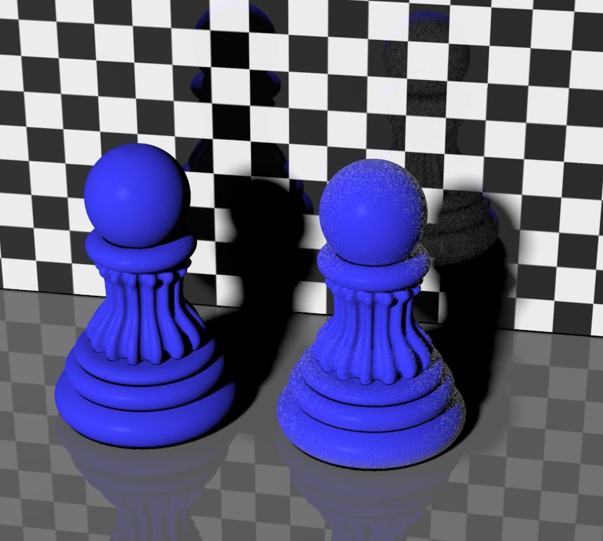
In the image below, the left pawn shows regular diffuse while the right pawn offers Gather as well, in an exaggerated way to illustrate the effects. The surface tries to attract light from surrounding objects and wants to bleed their color onto its own surface.

The surface having Gather shoots out rays to scan the neighborhood. Samples determines the ray-density (quality), MaxDist the maximum length of them. So colors from surfaces further away are not dealt with. When the surface has displacement maps, RayBias will make the first portion of them ignored to avoid time-consuming raytracing on the tiny details. Both MaxWidth and RayBias are in the units I’ve set in Global Preferences (which is Meters in my case). Altering my preferences will affect the values shown, but of course not the effect itself. When taking values from other sources, I might have to convert for unit differences.

In finding surfaces to pick up colors from, each surface element of the object looks around in outward direction (following its surface normal). Angle limits the directions in which it’s doing so, 180 means all outward directions.

Next >

What’s the Raytrace > Ambient Occlusion node used for?

Nodes are the essential building blocks in the Advanced interface to the Poser Material Room. They are the graphical representation of mathematical function calls, that is: calculation procedures which turn parameters (inputs) to a result (output).

Intermediate

When a direct light shines on an object, the light will get diffused, reflected and transmitted from that object surface. The object will cast a shadow to another object, or to parts of the same object, behind it. Shadow maps are a fast but limited way to derive such direct shadows at rendering, raytraced shadows are slower to derive but more accurate. Those shadows can be blurred somewhat to represent the size of the light source. And they can get a reduced shadow intensity to represent the ambient lighting levels from the environment. But the latter is just a trick to compensate for Posers inabilities to handle such effects from direct lighting only.

In the meantime, the industry developed an approach to resolve the issue: IBL or Image Based Lighting. A point source in the scene radiates light according to an image map, but in an inverse way: the light rays are not leaving the light to the outside, but travel from the outside towards the light as if a huge sky dome surrounding the scene emits this environmental light. Using a dome object with the image onto it enhanced the illusion of such a surrounding environment, whether it’s a sky or a shop interior.

Although that increased the quality of the lighting it did not answer a similar requirement for shadowing. As a result, Ambient Occlusion (AO for short) was born to get better shadows as well. Better as in: reduced by environmental lighting. That was at least some step forward from the (ab)use of Ambient for adjusting the lighting levels in an object specific way.

First, AO was implemented in Poser as a surface property which made the response to light dedicated to specific objects in the scene. Again, as an improvement over the use of Ambient for this. Then AO was implemented as a property of the light itself, effectively making the surface property obsolete. And after all, the entire IBL+AO concept was replaced by Indirect Lighting.

So, the Ambient Occlusion surface node is meant for scenes without IDL, without IBL, lit by direct point- spot- or infinite lights only, without AO enabled for those lights. When the scene gets lit by IBL (which has no shadows and no highlights) and some direct lights as well, AO should be enabled for those lights and the AO materials node should be dropped. When the scene gets lit by IDL, it should not have IBL lights or any AO materials nodes. Direct lights can give some support (like flashing outdoors, or representing a sun shining in) and their AO properties can help to improve on their shadows even more but should be used with care.

For short: the AO node can be considered outdated, and is available for compatibility only. Use the AO properties of lights instead.


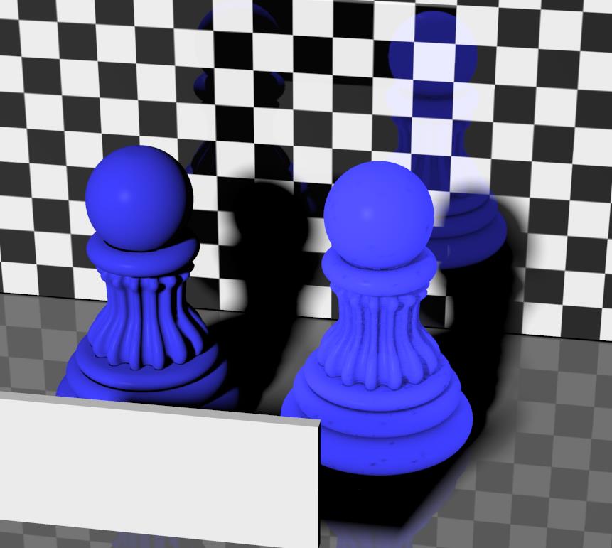
The left pawn shows regular diffuse, the right pawn has a (very limited) amount of AO assigned to the surface. It behaves like it glows a bit, and it hardly picks up shadows when an object blocks the light.

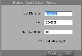
The surface having Ambient Occlusion shoots out rays to scan the neighborhood. Samples determines the ray-density (quality), MaxDist the maximum length of them. So shadows from surfaces further away are not dealt with. When the surface has displacement maps, RayBias will make the first portion of them ignored to avoid time-consuming raytracing on the tiny details. Both MaxWidth and RayBias are in the units I’ve set in Global Preferences (which is Meters in my case). Altering my preferences will affect the values shown, but of course not the effect itself. When taking values from other sources, I might have to convert for unit differences.

By default, AO is dealing with direct light only which is exactly what it’s made for, but by ticking the Evaluate in IDL, that can be changed.

As said, instead of using the node on a surface, the use of the light property is preferred.


When clicking the [ Scene AO Options ] button the generic AO settings unfold in which I recognize all the other AO options from the node. Except that Strength is a per light setting, and the other options are the same for all. Like in IDL lighting which replaces all IBL, AO and more, the effects are the same for all objects in the scene now, as it should be.

Next >

What’s the Raytrace > Refract node used for?

Nodes are the essential building blocks in the Advanced interface to the Poser Material Room. They are the graphical representation of mathematical function calls, that is: calculation procedures which turn parameters (inputs) to a result (output).

Intermediate

Abstractly spoken, any object surface is the separation of two volumes: the ‘inside’ part and the ‘outside’ part relative to the object. When both parts are transparent to some extent, a light ray can pass through the surface. And when both parts consist of different stuff, with a different ‘optical density’ (like air and water, water and glass, …) then the light ray gets bend at the surface because the speed of light is different at both sides.
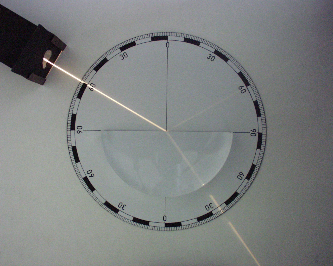
This is ‘refraction’, and by inventing an Index of Refraction (IOR), being 1.0 for vacuum, each material can have its own value defining its optical properties. In other words, the IOR defines the amount of refraction, the extent of light ray-bending, at the surface.

The image below illustrates transparency without refraction (left pawn) and refraction without transparency (right pawn). Without refraction the background image passes through undeformed, with refraction the pawn shows a glass-like behavior. As I can see, Poser refraction takes care of transparency all by itself (*).
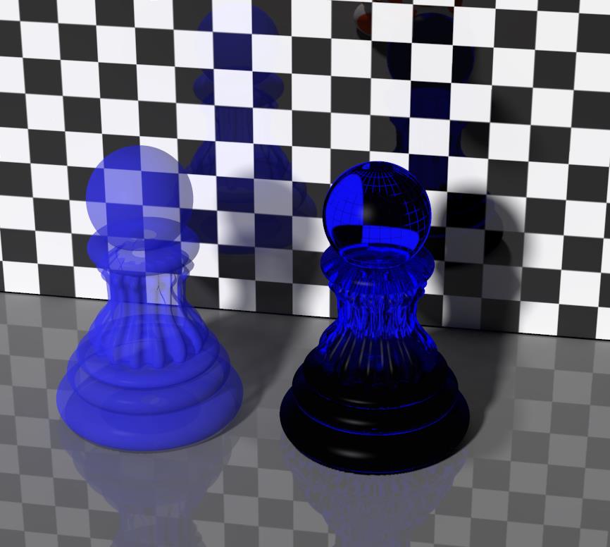
This Refract node adds accurate (*), raytraced refraction to the PoserSurface material definition. It requires Raytracing in Render Settings to be switched ON. The quality of the result depends on the ‘Number of Bounces’ set in Render Settings as well. Passing through a surfaces counts as a bounce, so entering and leaving a transparent object requires two bounces. The number set is a maximum value, when Poser does not need them it won’t use them, but if the number of bounces for a light ray exceeds this limit, the light ray is killed. This might speed up the rendering while it also might introduce artifacts (black spots) in the result. The tradeoff is mine, but as nature has an infinite number of bounces, the max value is the best when I can afford it.
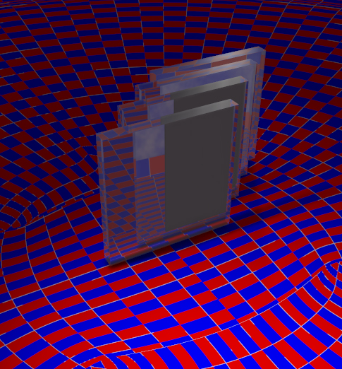
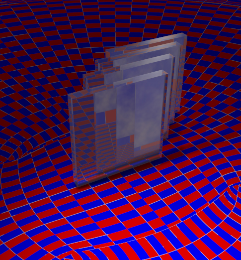
Left: Raytrace bounces set to 4, while 4 objects require 8 bounces. Right: When the value is increased to 8 or more, all objects and surfaces can be passed.

(*) Notes:

  • Refraction only handles the light from objects in the surrounding scene. It does not cater for the rays from direct light sources (spot, point, etc. lights), these will not get bend at all. Refraction does not work for light passing through an object shining onto another object: refractive objects behave opaque to direct light and make deep shadows accordingly. But Transparency behaves as expected, as discussed in other basic and advanced articles. In other words: basically Poser transparency and refraction are supposed NOT to be mixed, but in various cases you’ll need to. Mixing them will introduce a lot of issues, including a serious slowdown of rendering.
  • At the moment (Poser versions up till Poser 10 / Pro 2014 SR3) raytraced refraction is in error, as the ray leaving the object towards the camera is bend the wrong way. In real life, a light ray should bent ‘forward’ when entering the object, ‘backward’ again when leaving he object, and as a result it should continue its journey parallel to its original path but just shifted in space. Currently in Poser the ray bends in the same direction twice. It’s said to be repaired in Service Release SR4.

Practical use

I want to use refraction when a material represents liquid or glass, but in real life such transparent materials are reflective as well. And actually, those two phenomena are in a complex balance: the more refractive a material, the more reflective it will be too. On top of that, real life transparency and reflectivity both depend on the angle the camera looks at the surface. The skewer the angle, the more reflective the surface becomes, and the less light is left to pass through. That makes the surface less transparent (and not: less refractive, the bends will be the same). These combined issues are knows as the “Fresnel effect”, and supported in Poser by the Fresnel node and the Fresnel_Blend node.
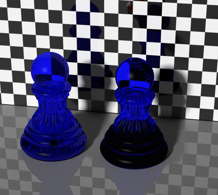

The right pawn still shows refraction as before, the left pawn shows Fresnel. Especially the upper edge of the left pawn clearly shows that Fresnel is not only transmitting the wall at its back, but also is reflecting it. Those reflections are missing on the right pawn.

About the Refract node parameters:
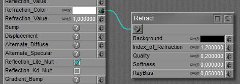
The Index Of Refraction is discussed above. Values for various materials can be found here.

Quality offers a tradeoff between speed and result; high values require longer render times but present crispier results. Softness increases the blur of the refracted image, representing irregularities, impurities and even minor movements and vibrations in the refracting surface.

RayBias is a special feature to address a special issue, regarding the refraction on image-based displaced surfaces. RayBias is a distance, in the Poser units as set in my User Interface preferences. The default is 0.3 inch or 0.007620 meters as in the screen grab above. Poser takes the refracting surface, moves it for this distance outwards from the object, then it calculates the refractions, and then it projects those refractions onto the surface of the object itself. This way, all irregularities of the refracting surface which are smaller than this distance are disregarded, usually these are caused by the details of displacement maps. It speeds up refraction calculations considerably, but it does introduce artifacts and less accurate refractions as a downside. For that reason, one should not have this value larger than the amount of displacement in the same PoserSurface material definition. The 0.3” (0.76cm) default value is quite a lot, actually.

Refraction Color (in the PoserSurface column) gives color to the material, like red to wine or sapphire. But do note that this is a surface effect only, like a colored plastic cover around the object. Poser cannot do volumetrics, the wine will be equally red whatever way I look at it, and the glass will be equally red whatever the thickness.

The contribution of refraction to the total surface definition will be made up from the combination of Refraction_Color * Refraction_Value. This does not hold for the refractive effect itself, which is determined by the IoR. To represent a dark colored material, I can either use a dark color in the swatch, or a low value. Note that Color will be affected by Gamma Correction, the Value will not so 80% White and 100% Value will behave different from 100% White and 80% Value under GC render conditions. For that reason, it’s recommended to leave Value at 1.0 and put all adjustments into the color swatch.

Rendering

Raytraced refractions and reflections are realistic, detailed, and although Poser performs them quite efficient they are time and resource consuming at render time. As a consequence, one should be careful not to put too many raytracing intensive challenges into one scene. InDirect Lighting (IDL) is such a challenge, having a lot of reflective and/or refractive surfaces in one scene is a challenge, having reflections and refraction (and especially Fresnel) on a complex surface is a challenge, and having Max Bounces (and the IDL Quality options) set high in Render Settings make a challenge as well. Take the Refraction vs Fresnel image shown above. It’s IDL, and reflective wall and floor, and quite high values in Render Settings. Rendering on a fast machine took 3.5 hours. Poser does have its limitations. There are no meaningful fast alternatives for refraction, like we have image-maps or environmental maps for reflections. Sorry for that.

On top of all those things, Poser raytracing is designed to work with a completely non-transparent surface; refraction caters for (full) transparency on its own. While doing so, raytracing works for objects in the scene only, it cannot handle direct light, nor the shadows or specularity thereof. Mixing raytracing with transparency however might produce unexpected or even erroneous results, while also taking render time to infinity.

Next >

What’s the Raytrace > Reflect node used for?

Nodes are the essential building blocks in the Advanced interface to the Poser Material Room. They are the graphical representation of mathematical function calls, that is: calculation procedures which turn parameters (inputs) to a result (output).
Intermediate

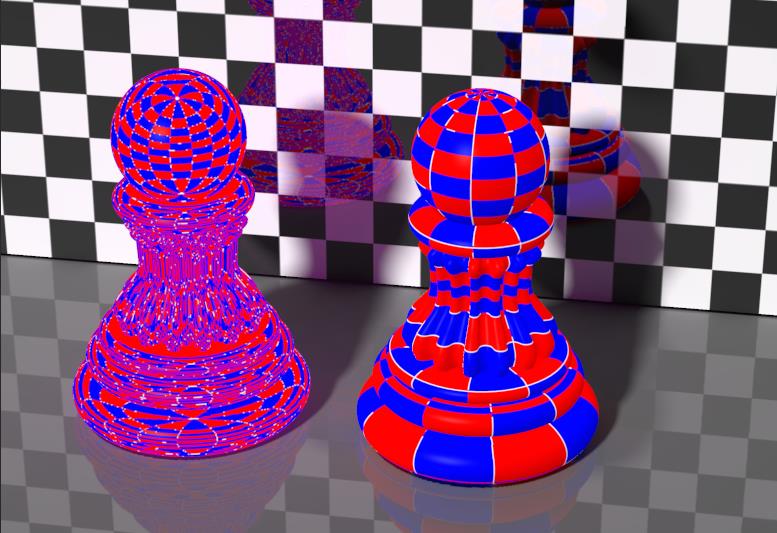
This Reflect node adds accurate, raytraced reflections to the PoserSurface material definition. It requires Raytracing in Render Settings to be switched ON. The quality of the result depends on the ‘Number of Bounces’ set in Render Settings as well. This number is a maximum value, when Poser does not need them it won’t use them, but if the number of bounces for a light ray exceeds this limit, this light ray is killed. This might speed up the rendering while it also might introduce artifacts (black spots) in the result.

Do note that Reflection only handles the light from objects in the surrounding scene. It does not cater for the rays from direct light sources (spot, point, etc. lights). This part is dealt with by Specularity. Reflection and Specularity are two portions of the same natural phenomenon: reflectivity. These two material properties should be balanced with respect to that, but since they have no parameters in common, that’s mainly a matter of taste and intuition. Effectively, I’m balancing the intensities a) of the direct lights and b) of the light bouncing from the objects, with respect to reflection.

Of course there must be something to reflect in the scene at the first place, and this sort of requires that my scene is build out far beyond and behind the scope of the camera. I probably don’t want to do that, and Background offers to possibility to supply an additional background color or image or texture node instead. In the screen grab above nothing is supplied, but turn the color swatch to white or grey and plug in the appropriate node instead, and the job is done.


The left pawn shows regular diffuse and specularity, the right pawn has reflection added to this.

The Quality parameter offers a tradeoff between speed and result; high values require longer render times but present crispier results. Softness increases the blur of the reflected image, representing irregularities, impurities and even minor movements and vibrations in the reflecting surface.

RayBias is a feature to address a special issue, regarding the reflections on image-based displaced surfaces. RayBias is a distance, in the Poser units as set in my User Interface preferences. The default is 0.3 inches or 0.007620 meters as in the screen grab above. Poser takes the reflecting surface, moves it for this distance outwards from the object, then it calculates the reflections, and then it projects those reflections onto the surface of the object itself.

This way, all irregularities of the reflecting surface which are smaller than this RayBias distance are disregarded; usually these are caused by the details of displacement maps. It speeds up reflection calculations considerably, but it does introduce artifacts and less accurate reflections as a downside. For that reason, one should not have this value larger than the amount of displacement in the same PoserSurface material definition. The 0.3” (0.76cm) default value is quite a lot, actually.

Reflection Color (in the PoserSurface column) usually works with white, unless I’m representing a metal. Metals have colored reflections, like Gold is yellow and Copper is red. The Reflection Value (PoserSurface as well) represents the reflectivity of the surface, and despite my experiences in nature, this value is quite low for most materials, except metals. Other articles on this include detailed colors and reflectivity values for various kinds of real-life stuff.

One note of caution: the final amount of reflectivity will be made up from the combination of Reflection_Color * Reflection_Value. To represent low reflectivity, I can either use a dark color, or a low value. But I should not do both! This is especially relevant for colored metals, where reflectivity becomes somewhat reduced simply but not using white in the color swatch.

Raytraced reflections are realistic, detailed, and therefore time and resource consuming. When I don’t need this level of accuracy, reflections can use a simple image map, or as a compromise, a Spherical Environment Reflection Map.

The raytraced reflections as presented by the Reflect node are not extremely photo-realistically accurate however. In real life, the amount of reflection depends somewhat on the angle the surface is looked at by the camera. Skew angles increase reflectivity. This is known as the “Fresnel effect”. It’s mainly visible for fluids and glasses.

Next >

What’s the difference between all those Scatter nodes?

Nodes are the essential building blocks in the Advanced interface to the Poser Material Room. They are the graphical representation of mathematical function calls, that is: calculation procedures which turn parameters (inputs) to a result (output).
Intermediate

Poser Material Room offers the following nodes

addressing scattering of light within an object surface (skin) layer.

From these, CustomScatter is the most generic, does require the SubSurface Scattering (SSS) option in the Render Settings, and provides direct access to all parameters of the mechanism. Which, by the way, are nice words telling that I’m on my own finding the appropriate values for them. As it actually deals with the light rays scattering within the surface layer, it takes the most resources and render time. And gives the ‘best’, most manageable results in return.

Subsurface Skin then is a derivative of CustomScatter, dedicated to (human) skin.

Scatter on the other hand offers the possibility to pick a preset, based on something similar to what I want to accomplish. It does not use the SubSurface Scattering option in the Render Settings, and so it takes (far) less time and resources for rendering, but the results might be somewhat less realistic. They are less manageable anyway, but is does resemble scattering to some extent.

The ones just mentioned above are available in Poser 8 / Pro 2012 and up. The ones mentioned below are available in earlier versions as well.

Skin itself is just a combination of regular material properties, dedicated to (human) skin. It presents the diffuse, specular and ambient properties of a Poser material in a balanced way and mimics the waxiness of skin in a classical way, as used in the earlier versions of Poser. It does not use the subsurface scattering as referred to in the Render Options.

FastScatter is an early, and simple – and according to the manual outdated – way of representing SubSurface Scattering. It does not use the subsurface scattering as referred to in the Render Options.

Next >