Material Room offers a Simple interface. What do I miss?

When using the Simple interface, I miss:

  • About anything more advanced than assigning color and an eventual image map to any feature. As a result, my render will keep that artificial, hard plastic-like feel.
  • The option to have Bump and Displacement both in one surface definition, and the option to use Normal maps. As a result, I cannot distinguish large scale (displacement) from small scale (bump) surface variations. And I can’t use Normal maps, which are common in shading game characters and objects.
  • Access to more real-life optical effects like Translucency and Refraction. As a result, creating believable glass and fluids will remain an issue.
  • Access to the Preview / Diffuse / Specular split in direct light properties As a result, I’ll keep on having issues with handling Indirect Lighting (IDL) in an appropriate way, in preview as well as in rendering.
  • Access to advanced render features (Custom_output) Honestly, these are hardly used anyway and can be considered high-end pro stuff.

Intermediate

Generally, all features which remain unsupported by the Simple interface, will also go unsupported when exporting Poser scenes and objects to other formats or programs. Exporting to OBJ, integrating Poser with LuxRender, Octane, Vue or you name it, all tend to lose the material properties which are not supported in the Simple interface. And even some of those might get lost in translation. In other words: when Poser is just my scene building and posing tool but not my final renderer, I consider the Material Room Simple interface as the recommended one. The question: what do I miss, can be inverted to : what elements from the Advanced interface go (un)supported by the Simple interface. This is addressed in the next article.

Next >

How do I access a Material?

The straightforward way is to use the Material tab to enter the Material Room. An object or part of it already can have been selected, or can be selected from within the room itself. The Material Room offers a Simple User Interface, as well as an Advanced one.

Intermediate

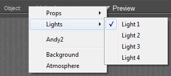
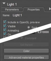
Next to that, there are some additional ways into Material Room, for the ‘material properties’ of Lights, Atmospheres, Backgrounds, and for some specific surface properties:

1)      When a Light is selected, its Properties tab offers an [Advanced material properties] button which brings me into the Material Room, for the coloring properties of that light.

2)      With menus File > Import > Background Picture or … > Background Footage,

and with the Shadow Color picker just right/below the Document window one affects the contents of the background material.

3)      From within Material Room some buttons on the right affect the object surface material at hand:

  • Add Reflection and Add Refraction
  • Add Skin Subsurface Scattering
  • Setup Shadow Catcher and Setup Toon Render

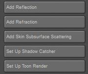
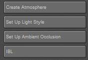
The [Create Atmosphere] button however affects the Atmosphere material, while the next buttons

  • Setup Light Style
  • Setup Ambient Occlusion
  • IBL

affect the various coloring properties for Lights.

Next >

What’s a material, a shader, a texture, a map?

In real life, a material is the stuff something is made of. Rock, brick, sand, knitted red wool, thin leaded glass, anything. Real life materials not only have a look, they also have a feel, a smell, and a response to our actions determined by a weight, flexibility, and the like.

In virtual life, like a Poser scene, a shader refers to a set of object (surface) properties that mimics the looks of a real life material, when rendered. So we can have a rock shader, a knitted red wool shader, etcetera. Shaders do not have a feel, or a smell, they’re inside the computer. But since everyone can tell real life from virtual, the word “material” is also used in these cases, at least in some software communities. So, in Poser one has a Material Room, to make a “brick material” and to assign it to a wall in the Poser scene. In Poser communities, “shader” is rarely used.

In real life, texture relates to the feel of the thing at hand. The surface roughness of the brick when I rub it with my hand, the structure of the fish I feel with my tongue when tasting it. In virtual life however, texture usually refers to the colors of an object surface. A texture then is an image used to assign such colors to elements in my Poser scene. However, since people are somewhat relaxed in their choice of words, they’re happy to assign a “brick texture” to a wall; not only implying color but roughness and reflectivity as well. So in those cases texture means material means shader.

While texture usually refers to an image which is used to assign colors to a surface(property), a map refers to an image which is used to vary the amount of something. A bump map to vary the amount of roughness, a transparency map to vary the opaqueness, and so on. Maps in those cases tend to be black & white, which refer to 0% .. 100% and have greyscales for everything in between.

On the other hand, mapping (as in: UV-mapping) is the term for assigning images in general to an object surface whether it’s for coloring or for determining roughness or reflectivity. So some people might use “map” while referring to the image driving the coloring process too. Fortunately, there is some method in this madness: as shader is hardly used in the Poser community, material or texture is used instead. The people using material for the whole thing tend to use texture for the coloring images. The people using texture for the whole thing tend to use texture-map for the images. But be aware; without context or background info, “brick texture” still might mean either the whole thing or just the color-driving image.

Next >

Poser Materials I – Introduction

The articles in this section discuss some terminology, and the various interfaces to the materials definitions:

Next subsections present articles on defining the surface properties of objects, on a (II) Simple , (III) Intermediate and (IV) Advanced level, as well as on defining the properties of (V) Non-objects (atmosphere, background, lights) as far as these are handled through the Material Room interface. The Appendix lists all Material Room nodes and relevant Render Settings, and their availability in the various Poser versions.

Poser Material Concepts & Elements

The content of this entire section can be downloaded in two versions

  • FULL version, PDF 8.7Mb covering it all
  • BASIC version, PDF 0.8Mb covering only subsections I and II, for starting Poser users

This Concepts & Elements section discusses to some extent the buzzwords, the interactions with Poser Lighting and with the Poser Firefly renderer, and the way things work (together), all as far as the Poser Material Room is concerned. It discusses intensively the technical details of all elements that build the shader definitions within the Material Room.

That’s quite a lot, and for that reason the information is presented in various subsections:

I Introduction

The articles in this section discuss some terminology, and the various interfaces to the materials definitions:

II Simple Surface Definitions

The articles in this section discuss material definitions for object surfaces, which can be handled through the Simple Interface, and do not require a deep understanding of Material Room principles. Each article however also presents the Intermediate approach, using the Advanced interface for the same subject at hand. This is to avoid multiple articles answering the same question.

III Intermediate Surface Definitions

The articles in this section discuss some material definitions for object surfaces (the PoserSurface), which are handled through the Advanced Interface: the nodes from the Lighting group, and the nodes on image-maps and movies. It also discusses some principles on dealing with the PoserSurface root node.

  • From here on, articles discuss the workings of the PoserSurface root node in general.
  • From here on, articles discuss some elaborate details of components available in the Simple interface: diffuse shading, reflection details, render settings.
  • From here on, articles discuss the additional components of the PoserSurface node, like Translucency, Refraction, ToonID and the like.
  • From here on, articles discuss Alternate_Diffuse, Alternate_Specular and all the nodes from the Lighting > Diffuse and Lighting > Specular groups.
  • From here on, articles discuss the nodes from the Lighting > Special group, like Scatter and Hair. In this article the various scatter nodes are compared.
  • From here on, articles discuss the nodes from the Lighting > Raytrace group. In this article their complex relationship with Transparency is dealt with.
  • From here on, articles discuss spherical mapping, image maps and movie-based textures.

IV Advanced Surface Definitions

The articles in this section discuss all Material Room nodes required for either procedural textures, and the ones explicitly aimed at node-tree building.

A procedural texture is not derived from an (eventually color filtered) external image or movie still, but is mathematically generated internally from surface or spatial coordinates. The nodes to accomplish such textures can be found in the 2D Textures and 3D Textures groups.

Materials are applied to objects, objects parts and more precise: to specific Material Zones within those objects and parts. This article discusses the details.

Material Room supports the creation of quite elaborate node-trees, like a programming language into material definitions. This section will not address the art of such programming itself, but will present and discuss the building blocks alone. These can be found in the Variables  and Math groups.

V Materials for Non-Objects

The articles in this section discuss properties for Scene Atmosphere, Scene/render Background and Lights Coloring. These are not objects with a surface, but do have properties which are handled in Material Room. These properties can be accessed via the Object selector.

Most of those topics are considered Intermediate level, although various configurations can be setup via Material Room menus, and can be managed through the Simple interface. On the other hand, managing the details of a scene Atmosphere requires the use of nodes from the 3D Texture group, which by itself is considered Advanced.

This section concludes with some varied, advanced topics like mapping for IBL , Gamma Correction (GC) and GC on Transparency. The Appendix lists all Material Room nodes and relevant Render Settings, and their availability in the various Poser versions.

Managing Poser Scenes (02. Camera Intro)

The Poser camera is my eye into the virtual world. There are various kinds of special purpose cameras available, and (via menu Object \ Create Camera) I can add new ones.

The Left / Right, Bottom / Top, Front / Back cameras are “orthogonal” or “2D”. This means that an object keeps its apparent size independent of the distance to the camera, which is bad for believable images but great for aligning objects and body parts. These cameras help me positioning props and figures in the scene.

All other cameras are “perspective” or “3D” ones which mean that objects at a larger distance appear smaller.

Two objects with some distance As seen by the Left (2D) camera As seen by the Main (3D) camera

The Posing, Left/Right-hand and Face cameras are constrained to the selected figure, and meant to support the posing of body and hands, facial expressions and the precise positioning of hair and jewelry. These cameras help me creating figures the right way. This implies that when I change figure in the scene, the Posing, Hand or Face camera will show something different immediately.

The Shadow Cams help me aiming spotlights. The camera looks through the lamp into the scene which gives me a fine way positioning those lights. For Infinite lights and Point-lights such an aid is far less relevant.

Camera type

Poser gives me, in each new scene, three cameras to walk through the scene, perform inspections, and take other points of view and everything. These are the Main cam, the Aux-cam (both of the Revolving kind) and the Dolly cam (of the Dolly kind).

Revolving cameras live in Poser space. They rotate around the center (0,0,0) and around the Poser X,Y,Z axes through that center. The angles are called x-, y- and zOrbit. They move according to their own local axes, so when such a camera looks down, an Y-translation makes it move sideways, not up or down. More precise: the camera origin rotates as stated and the camera itself translates against that origin. This is very satisfying from a computational point of view, but very confusing for us, humble human users.

Dolly cameras live in their own space, rotate around their own center and their own axes, like any other regular object. Roll means rotating around the forward axes, like a plane taking a turn. Pitch means rotating around the local left-right axes, making the nose of a ship (or plane) going up and down. Yaw means rotating around the local up-down axis, which is what makes people seasick. They move according to the Poser X,Y and Z axes so if I alter the DollyY value they just move up or down, whatever they’re looking at.

Main and Aux represent nearby and away director overview cams, fixed to the studio. The photographers’ camera, moving through the scene, even animated maybe, and shooting at various angles at will, is best represented by a Dolly camera. So when I create a new, I choose the Dolly kind. Their transform parameters (move, rotate) are easier to understand and especially their animation curves are easier to interpret.

To add some artistic words on camera angle:

  • * I keep the horizon straight, especially in landscapes, unless I’ve good artistic and dramatic reasons not to. The reason is that my audience looking at my image will have a problem identifying themselves with the photographer when they have to twist their neck. In Poser camera terms: don’t Roll.
  • * I shoot straight, in Poser camera terms: I don’t Pitch either. This is interesting because most people tend to take pictures while standing upright and have the camera angle being determined by the position and size of the object. Animals, kids and flowers tend to be shot downwards while basketball players, flags and church bells tend to be shot upwards. So boring, so predictable: we see things in that perspective every day.

Focal length

Now let me put the camera at some distance of the scene or the subject. Depending on what I want to accomplish in my image, I have to zoom in or out by adjusting the focal length. The “normal” focal length for modern digital consumer cameras is 35mm, for analog cameras it was 50mm, and for current Hasselblads it’s 80mm. So, 50mm is considered wide angle for Hasselblad, normal for outdated analog and mild zoom for consumer digital. Poser follows the route of consumer digital. The 55mm initial setting for the Main camera is good for groups and studio work but needs zooming for portraying. The Dolly camera initially reads 35mm, the Aux camera reads 25mm which fits to its overviewing role. New cameras are set to 25mm initially and do need adjustment.

Perhaps you’ve noticed that in real life the modern consumer digital cameras are quite smaller, and especially quite thinner, than the older analog ones. You may know – otherwise: have a look at the hasselblad.com – that pro cameras are bigger. And yes indeed, there is a simple proportional relationship between camera size and its normal focal length. Poser supports this relationship to some extend: take the Main camera, and increase the Scale to 150%. You will see it is zooming out, while keeping the same value for its focal length.

Scale 100%, F=75mm Scale 150%, F=75mm

A larger camera needs a larger focal length to establish the same amount of zoom. But Poser is cheating a bit, which can be seen when I use the Aux camera to watch the behavior of the Main Cam. When scaling up the Main cam, it not only grows but it also moves back from the scene, while keeping its DollyX,Y,Z intact.

Scale 100%
Scale 150%

This is because a Poser Main or Aux camera is the whole thing from 0,0,0 to the view plane capturing the image, and it’s that whole thing which is scaling.

A camera which moves back while the DollyX,Y,Z values remain intact should ring a bell: apparently things are measured in “camera units” which are scaling as well. And indeed: the Focal Distance changes too. Try it:

  • Just Andy, just the Main cam, and you’ll find Andy at 11,7 (mtr).
  • Scale the Main cam to 150%, and you’ll find Andy’s Focal Distance at 7,8 (mtr) = 11,7 / 150%.

So while the camera retracts the focal distance DEcreases. Sometimes, Poser is black magic.

Another magical thing: some Poser cameras can scale, others cannot. Main, Aux, Dolly and even Posing cams can scale, but L/R-hand and all user added cams cannot. To some extent, this is a good thing because from the above we learn to watch camera scale as it might present more problems and unexpected results than is does any good. Since I take the habit of shooting my final renders with my own cam, instead of a build in Poser one, I don’t run this risk.

On top of that, cameras show a Focal and a Perspective parameter. Actually, the orthogonal Left/Right etc cameras show a Perspective setting only and go berserk when I try to change it. Other cameras, like the Dolly cam, show the Focal parameter only. Other cams, user added ones included, show both, and both parameters consistently show the same value. So, what’s up?

Perspective

Have a look at this simple scene, where I enlarge the focal length while walking backwards so Blue Andy remains about the same size in the shot.

20mm (scale 100% fStop=5.6):

35mm: 55mm:
80mm: 120mm:

As you can see, zooming in not only gives a smaller (narrowed) portion of the scene, it also brings the background forward. In other words: zooming flattens the image.

Actually, while zooming in I’ve got to walk backwards quite a lot, which might be undesirable in various cases. This is where the Perspective parameter comes into play. When changing the Perspective from 55 to 120 (218%), I will notice a change in camera size (scale 100 => 218%, zooming out) and a drop in the DollyX,Y,Z values (of 1/ 218%). The scaling enlarges the “camera distance unit” so this change in Dolly values actually makes me stay in the same position in the scene. At the same time the focal length goes up, zooming in. In order to keep Blue Andy about the same size in the image I still have to walk backwards, but far less. Simply, if I use the old 100% DollyXYZ numbers, I’m standing in the right place, Blue Andy has its original size but the perspective of the scene is that of the 120mm zoom lens.

Again: when I change the Perspective (instead of the focal length dial) and I keep the DollyZ etc values intact, then the foreground of the scene remains the same while the background comes forward, while I slowly moves backward myself, and so on. Even the focal distance can keep its value, as it’s measured in the same “camera distance units”.

If you keep standing in place and take the DollyZ as the Perspective dials presents to you, don’t forget to reduce the focal distance (in this example: with 1/218%, or from say 6 to say 3). This, for whatever reason, is not done by the Perspective dial.

Note: some Poser cameras (e.g. L/Rhand cam) have no Scale parameter, but I might change Perspective. This only changes focal length, so I just use that one instead. Scale remains at 100%. Some Poser cameras (e.g. Dolly cam) have no Perspective parameter, but I might change Scale by hand (and DollyX,Y). Some Poser cameras lack both, so I cannot use this Perspective feature at all. This is the case in user added cameras. When I use one of those for my final imaging I don’t have to bother on Scaling and Perspective tricks and troubles. I just cannot turn my digital consumer cam into a Hasselblad by spinning a dial.

Next >>

Managing Poser Scenes (03. Camera Blur & Parameters)

Like a real-life camera, the Poser camera presents us: Focal or Lens Blur (sharpness limits), Motion Blur (speed limits), Field of View (size limits) and even more limits.

Focal Blur

Focal Bur, or Depth of Field, is in reality the result of focal length, diaphragm (fStop) setting and shutter speed, while also fStop, shutter speed and film speed (ISO) are closely related. In Poser however, there is no such thing as film speed, and the Depth of Field is determined by the fStop setting only. Whatever the shutter speed, whatever the focal length, they won’t affect the focal blur.

20 mm, fStop 1.4: 120mm, fStop=1.4:

In a real camera, the change in focal length would have brought Pink Andy and the back wall in a sharp state as well. In Poser, the blur remains the same. And because the back end of the scene is brought forward when enlarging the focal length, the blur even looks like it’s increasing instead of the other way around.

Motion Blur

Shutter Open/Close both have values 0 .. 1, Close must be later that Open. The shutter time is measured in frame-time, so if my animation runs at 25 fps the frames start at 0.00; 0.04; 0.08; then Open=0.25 means the shutter opens at 0.01; 0.05; 0.09 or: 0.25 * 1/25 = 0.01 sec after frame start. Similarly, Close=0.75 means that the shutter closes at 0.03; 0.07; 0.11 or 0.75 * 1/25 = 0.03 sec after frame start and therefor 0.02 or 1/50 sec after Open. Contraring to real-life cameras, shutter time does not affect image quality like depth of field, it only affects motion blur or: 3D / spatial blur, in animation but in stills too.

So, a shutter speed of 1/1000 sec translates to a 0.030 value in a 30 fps animation as 0.030 / 30 = 0.001. For stills without motion blur, I just leave the defaults (0 and 0,5) alone. For anything with motion blur, I should not forget to switch on 3D Motion Blur in the Render Settings.

More parameters

The other two parameters: hither and yon, have no physical reference. They mark the clipping planes in OpenGL preview only. Everything less than the hither distance will be hidden, and everything beyond the yon distance will not show either. That is: in preview and in preview render, when OpenGL is selected as the delivery mechanism. Not when using Shreed (the software way of getting previews), not when rendering in sketch mode, not when using Firefly.

Hither = 1, Yon = 100 Hither = 10, Yon =20, near and far ends don’t show in preview. They do show in Firefly render.

This can have a surprising effect. When the camera is inside an object, but less than the hither distance away from the edge, you won’t notice it in the preview because the objects mesh is clipped out. But when you render, the camera is surrounded by the object and will catch no light. This gives the “my renders are black / white / … while I have the right image in preview” kind of complaints.

It sounds stupid: how can one land the camera inside an object? Well, my bets are that it will happen to you when you’re into animation. Smoothing the camera track will give you some blacked-out frames. Previewing the camera track through the Aux camera, and/or adding a ball object on top of the camera entry point (watch shadows!!) can help you to keep the view clear. Just setting the camera to Visible in the preview might not be enough.

Having said that, let’s have a look at the various camera properties.

  • * Focal (length) refers to zooming
  • * Focal Distance and fStop refer to focal blur, and requires Depth of Field to be switched ON in the render settings.
  • * Shutter Open/Close refer to motion blur, which requires 3D Motion Blur to be switched ON in the render settings.
  • * Hither and Yon set limits in the openGL preview.
  • * Visible implies that I can see (and grab and move) the camera, when looking through another one. By default it’s ON.
  • * Animating implies that changes in position, focal length etc. are key framed. Great when following an object during animation, but annoying when I’m just trying to find a better camera position during an animation sequence. I tend to switch it OFF.
  • * And I can disable UNDO per camera. Well, fine.


Field of View

In order to determine the Field of View for a camera, I build a simple scene. Camera looking forward, and a row of colored pilons 1 mtr at the right of it, starting (red pylon) at 1 mtr forward. So this first pylon defined a FoV of 90°. The next pylon (green) was set another 1 mtr forward, and so on. Then I adjusted the focal length of the camera until that specific pylon was just at the edge of the image.

Pylon Color Focal(mm) FoV (°) Pylon Color Focal(mm) FoV (°)
1 Red 11 90,0 9 Blue 115 12,6
2 Green 24 53,1 10 Red 127 11,3
3 Blue 36 36,8 11 Green 140 10,3
4 Red 49 28,0 12 Blue 155 9,4
5 Green 62 22,5 13 Red 166 8,7
6 Blue 75 18,8 14 Green 178 8,1
7 Red 87 16,2 15 Blue 192 7,6
8 Green 101 14,2


For simple and fast estimates, note that (pylon nr) * 12,5 = Focal(mm), like 6 * 12.5 = 75, where (pylon nr) is (meters forward) at one meter aside. As an estimate. I can use this for further calculations, e.g. on the size of a suitable background image.

Example 1

I use a 35mm lens, which gives me a 36-40° FoV, and my resulting render measures 2000 pixels wide. Then a complete 360° panorama as a background would require 2000 * 360/36 = 20.000 pixels at least, and preferably 40.000 (2px texture on 1 px result). With a 24mm lens the preferred panorama would require 2* 2000 * 360/53.1 = 27,120 pixels.

Example 2

In a 2000 pixel wide render, I want to fill the entire background with a billboard-like object. For quality reasons, it should have a texture of 3000 (at least) to 4000 (preferably) pixels. When using a 35mm lens, every 3 mtr forward sets the edge of the billboard 1 mtr left, and the other edge 1 mtr right. Or: for every 3 mtr distance from the camera, the board should be 2 meters wide. At 60 mtrs distance, the board should be 40 mtrs wide, left to right, and covered with the 4000 pixel image.

Non-Automatic

Modern real life cameras do have various modes of Automatic. Given two out of

  • sensitivity (ISO, film speed),
  • diaphragm (fStop) and
  • shutter speed (open time)

the camera adjusts the third one to the actual lighting conditions, to ensure a proper photo exposure.

Some 3D render programs do something similar, like the Automatic Exposure function in Vue.

Poser however, does not offer such a thing and requires exposure adjustment in post. For instance by using a Levels (Histogram) adjustment in Photoshop, ensuring a compete use of the full dynamic range for the image. Poser – the Pro versions – on the other hand, support high end (HDR/EXR) image formats which can survive adjustments like that without loss of information and detail.

The Poser camera is aware of shutter speed, but it’s used for determining motion blur only and does not affect image exposure. The camera is also aware of diaphragm opening, but it’s used for determining focal blur only and again, it does not affect image exposure. The camera is not aware of anything like film sensitivity, or ISO. It’s not ware of specific film characteristics either (render engines like LuxRender and Octane are). With this respect, the Poser camera is limited as a virtual one.

Next >>

Managing Poser Scenes (04. Camera Lens Effects)

In real life, a camera consists of an advanced lens system, a diaphragm and shutter mechanism, and an image capturing backplane. The diaphragm (relates to focal blur of Depth of Field), and the shutter speed (relates to Motion Blur or 3D Blur) were discussed already, and the role of the backplane is played by the rendering engine (which will be discussed in other sections of these Missing Manuals).

Something to note when emulating realistic results, is the relationship between things, which is not looked after by Poser itself. Doubling the sensitivity, speed or ISO value of the backplane increases the visibility of noise / grain in the result, and for the same lighting levels in the result it also doubles the shutter speed (is: halves the net opening time), or reduces the diaphragm opening (or: increases the fStop with +1), or reduces the Exposure (in Poser: halves the value, in Vue: reduces with -1.00).

Hence, when I show pictures of a dark alley, people expect more motion blur (longer shutter time) and/or more grain. When I show a racing car or motor cycle at full speed, people expect a shallow depth of field, and grain too. And so on. Poser is not taking care of that. I have to adjust those camera settings and post processing steps myself.

The other way around, portraits and especially landscapes can do with longer exposure times, and will show nearly no grain in the image and hardly any focal blur (infinite depth of field). And most lenses have their ‘soft spot’ (sharpest result) at fS=5.6 (sometimes 4), by the way.

This leaves us with the lens system. In real life a physical thing, with some weight as well. Physical things have imperfections, and these will “add” to the result. Since the lens system sits between the scene and the image capturing backplane, those additions are added on top of the image. In other words, those imperfections can be added in post, on top of the render. Again, the imperfections are required to make a too perfect render look as being captured by a real camera, adding to the photorealism of the image. When you don’t want photorealism, don’t bother at all.

In the first place, the lens system is a tube and therefor it captures less light at the edges. This is called vignetting. A dark edge on the picture, very visible in old photographs. Modern systems on one hand have better, brighter lenses, and on the other hand the lenses are just a bit wider so the vignetting takes place outside the capturing area.

Vignetting is a must – like scratches – on vintage black and whites.

Second, the lens system consists of various glass elements. This introduces reflections, either within the element (scattering) or on the elements surfaces. The internal, scattering reflections blur the small bright areas of the image, known as glare. The external reflections generate the series of circles or rings, known as flare. The flare shapes can be pentagonal (5-sides), hexagonal (6-sides) or more to circular, this is determined by the shape of the diaphragm.

Glare, the light areas are glowing a bit

Flare, making rings around the bright spots

Flares always exist from a very bright light within the scene towards the middle of the image. The more elements are present in the system, the more reflections we’ll see. Note that fixed length lenses have far less elements than flexible zoom systems.

Another effect, called bokeh, appears when a very dark, blurred background contains small strong highlights. While they take the shape of the diaphragm (like flares) they scatter around in the lens system. Normally they would not be visible, but they are since they are quite strong and the background is dark and blurred. While flare usually occurs in shots with no focal blur (or: infinite depth of field, outer space is a typical example), bokeh requires the background blur due to depth of field / focal blur. In most cases there is an object of focus and interest in the foreground. So, one cannot have flare and bokeh in one shot.

Bokeh Star flare

Third, the diaphragm itself can be the source of distortions: star flare. This usually happens when there are strong highlights in (partially) bright images, where the diaphragm is about closed due to a high fStop number. This tiny hole in the wall refracts light along its edges. A six-piece diaphragm will create a six-pointed star.

Note that the conditions for flare and star-flare contradict: flare needs an open diaphragm due to the dark background (like outer space) while star-flare requires a closed diaphragm due to the bright environment (sun on a winters day). The well-known sci-fi flares (Star Trek), having circular flares ending in a starry twinkle, are explicit fakes for that reason alone. One cannot have both in the same shot.

All these effects can be done in post, after the rendering. Sometimes you need Photoshop for it, perhaps with a special filter or plugin. Vue can do glare and both flares (but not bokeh) as part of the in-program post-rendering process.

Note: some people use flare as a container concept: everything that is causing artifacts due to light shining into the lens directly. Glare, flare, star-flare and bokeh are just varieties of flare to them. No problem, it’s just naming.

Next >>

Managing Poser Scenes (05. Camera Stereo Vision)

Once I manage to get images out of my 3D software like Poser or Vue, I might ask myself: “can I make 3D stereo images or animations as well, like they show on 3D TV or in cinema?” Yes I can, and I’ll show you the two main steps in that process.

Step #1 is: obtain proper left-eye and right-eye versions of the image or animation
Step #2 is: combine those into one final result, to be displayed and viewed by the appropriate hardware

Combining Left- en Right Images

In order to make more sense out of step 1, I’ll discuss step 2 first: how to combine the left- and right eye images.

Anaglyph Maker

For still images, this can be done in a special program like the Anaglyph Maker, available as a freebee on the internet http://www.stereoeye.jp/index_e.html. It’s a Windows program. I unpack the zip and launch the program, there is nothing to install. Then I load the left and right images

And I select the kind of 3D image I want to make, matching my viewing hardware. The Red-Cyan glasses are most common, as Red and Cyan are opposite colors in the RGB computer color scheme. Red-Green however presents complementary colors for the human eye but causes some confusion as Magenta-Green are RGB opposites again. Red-Blue definitely is some legacy concept.

When I consider showing the result on a interleave-display with shutter-glasses, or a Polarization based projection scheme, Anaglyph Maker can produce images for those setups as well. Those schemes do require special displays but do not distort the colors in the image, while for instance the Red-Cyan glasses will present issues reproducing the Reds and Cyans of the image itself. This is why images in some cases are turned into B/W first, giving me the choice between either 2D color or 3D depth. Anaglyph Maker offers this as the first option: Gray.

I can increase Brightness and Contrast to compensate for the filtering of the imaging process and the viewing hardware, and after that I click [Make 3D Image].

Then I shift the left and right images relative to each other until the focal areas of both images coincide. The best way to do that is while wearing the Red-Cyan glasses, as I’ll get the best result immediately.

Now I can [Save 3D Image] which gives me the option of saving the Red-Cyan result

Or the (uncolored) left and right images, which are shifted into the correct relative positions.

Photoshop or GIMP or …

Instead of using special software, I can use my imaging software instead. For single stills this might be tedious but for handling video or animations it’s a must, as there is no Anaglyph Maker for handling all movie frames in one go, while Premiere or so are quite able to do that. And then I’ve got my own 3D stereo movie.

  1. 1. Open the Right-eye photo (or film)
  2. 2. Add a new layer on top of it, fill it with Red (255,0,0) and assign it the Screen blending mode
  3. 3. Open the Left photo (or film) on top of the previous one
  4. 4. Add a new layer, fill it with Cyan (0,255,255) and assign it the Screen blending mode
  5. 5. Merge both top layers (the Left + Cyan one) into one layer and assign this result the Multiply blending mode. Delete the original Left+Cyan layers, or at least make them invisible
  6. 6. Shift this Left/Cyan layer until the focal areas or the Right/Red and this Left/Cyan combi align
  7. 7. Crop the final result to lose separate Red/Cyan edges, and save the result as a single image.

Please do note that I found that images with transparency, like PNG’s, present quality issues while non-transparent ones (JPG’s, BMP’s) do not. Anaglyph Maker supports BMP and JPG only. I can swap Left and Right in the steps above, as long as the Right image is combined with a Red layer (both start with ‘R’, to easy remembering), as all Red-Cyan glasses have the Cyan part at the right to filter the correct way.

Obtaining Left-eye and Right-eye images

Although in real life dedicated stereo cameras can be obtained from the market, this is not the case for 3D software like Poser or Vue, so I’ve got to construct one myself. Actually I do need two identical cameras, a left-eye and a right-eye one, at some distance apart, fixed in a way they act like one.

(Image by Bagginsbill)

The best thing to do then is to use a third User Cam, being the parent of both, and use that as the main view finder and if possible, as the driver of the settings of both child cameras.

Such a rig guarantees that camera movements (focal length adjustments, and so on) are done in sync and are done the proper way. Like rotations, which should not take place around each individual camera pivot but around a pivot point common for both eye-cameras. In the meantime, the User Cam can be used for evaluating scene lighting, composition, framing the image and so one before anything stereo is attempted.

Les Bentley once published a Stereo Camera rig on Renderosity. You can download it from here as well, for your convenience. Please read it’s enclosed Readme before use.

Now I’ve grasped the basic principle, the question is: what are the proper settings for the mentioned camera rig? Is there a best distance between the cameras, and does it relate to focal length and depth of field values? The magic bullet to these questions is in Berkovich Formula:

SB = (1/f – 1/a) * L*N/(L-N) * ofd

This formula works for everything between long shot and macro take, is great for professional stereoscopists working in the movie industries, and helps them to sort out the best schemes for anything from IMAX cinema to 3D TV at home, or 3D gameplay on PC. It relates the distance between both cameras, aka the “Stereo Base” SB with various scene and camera settings:

  • * f – focal length of the camera lens (as in: 35mm)
  • * a – focal distance, between the camera and the “point of sharpness” in the scene (as in: 5 meters = 5000mm).
  • * L, N – refer to the nearest and farthest relevant objects in the scene, as in: 11 resp 2 meters. On the other hand, both can be derived from Depth of Field calculations, given focal distance and f-stop diaphragm value.
  • * ofd – on film deviation, as in: 1.2mm for 36mm film. What does it mean? When I superimpose the left- and right-eye shots on top of each other, and make the far objects overlap, then this ofd is the difference between those shots for the near objects. Or when I superimpose the shots on the sharp spot (as I’m expected to do in the final result), then this ofd is the deviations for the near- and far objects added together. This concept needs some translation to practical use in 3D rendered images though. I’ll discuss that later.

So for the presented values: SB = (1/35 – 1/5000) * 11*2/(11-2) * 1,2 = 0,083 meters = 8,3cm which coincides reasonably with the distance between the human eyes.

For everyday use in Poser or Vue, things can be simplified:

  • * the focal distance a will be much larger than the focal length f as we’re not doing macro shots, so 1/a can be ignored in the formula as it will come close to 0
  • * the farthest object is quite far away from the camera, so L/(L-N) can be ignored as it will come close to 1
  • * the ofd of 1.2mm for 36mm film actually means: when the ofd exceeds 1/30th of the image width we – human viewers – get disconnected from the stereo feeling, as the associated StereoBase differs too much from the distance between our own eyes.
  • * It’s more practical to use the focal distance instead of the distance to the nearest object, as focal distance is set explicitly for the camera when focusing.

As a result, to make the left and right eye images overlap at the focal point, one image has to be shifted with respect to the other, for

(Image shift) = (Image width) * (SB * f) / (A * 25)

With image shift and image width in pixels, StereoBase SB and focal distance A in similar units (both meters, or both feet), and focal length f in mm. For instance: with SB=10 cm = 0.1m, f=35mm and A=5 mtr a 1000 pixel wide image has to be shifted 1000 * 0.1 * 35 / (5 * 25) = 28 pixels.

For a still image, I do not need formulas or calculations as I can see the left and right images match while nudging one image aside gradually in Photoshop. But in animations, I would not like to set each frame separately. I would like to shift all frames of the left (or right) eye film for the same amount of pixels, even when focal length and focal distance are animated too. This can be accomplished by keeping SB * f / A for constant, by animating the StereoBase as well.

Next >>

Managing Poser Scenes (06. Rendering Intro)

Like the Poser Camera can be seen as the virtual equivalent of a real-life camera front-end: the body + lens & shutter system, so can the Poser Renderer be seen as the virtual equivalent of the real-life camera backend: the backplane, or film / CCD image capturing device.

The captured image itself is determined by the camera Field of View, the Poser backend does not auto-adjust to lighting variations; it offers a fixed sensitivity. A 100% diffuse white light plainly lighting a 100% diffuse white object will create a 100% white lit area in the result. Adding more lights, and/or adding specular lighting on top of this will make the image overlit: higher lighting levels get clipped and details will get lost.

Given image contents, the Poser Renderer has an adjustable resolution: I can set about any image size in pixels, maintaining the Field of View. Poser Pro also supports 16-bit-per color (HDR, EXR) image output to ease enhancements of low lighting levels in post, and also supports various forms of render passes: splitting the result into separate images for separate aspects of the image, to ease advanced forms of post-processing (see my separate Poser Render Passes tutorial). A real-life camera can’t do all that.

Rendering takes time and resources, a lot. Rendering techniques therefor concentrate on the issue: how to get the most out of it at the least costs. As in most cases, you and me, the users themselves, and our processes (workflows) are the most determining factor. Image size, and limits on render time come second. Third, I’ll have to master the settings and parameters of the renderer. And last but not least I can consider alternatives for the Poser Firefly renderer.

Render habits

In the early days, computers were a scarce resource. Therefore, programmers were allowed to make three tests maximum before their compiled result proved flawless, and could be taken into production. At present, computing power is plenty, and some designers press the Render button about every 5 minutes to enjoy their small progress at the highest available quality. For 3D rendering, any best practice is somewhere in the middle.

Rendering takes time and resources, a lot. But modeling, texturing, and posing (staging, framing, animating) do take a lot of time as well. Therefore it makes sense to put up some plan, before starting any project of some size. Not only for pros on a deadline, having to serve an impatient client. But for amateurs or hobbyists like me as well or even more so, since we don’t have a surplus of spare time and don’t like to be tied to the same creative goals for months.

First, especially in animating, I concentrate on timing, framing (camera Point of View) and silhouettes. In stills, my first step should be on framing, basic shapes, and lighting – or: brightness levels and shadowing. Second, colors (material hues) and some “rough details” (expressions) kick in. Third, material details (shine, reflection, metallic, glass, stains, …), muscle tones, cloth folds (bump, displacement) enter the scene. And finally, increasing render quality and similar advanced steps become worthwhile, but not before all steps mentioned above are taken up to a satisfying intermediate result.

In the meanwhile, it pays off to evaluate each intermediate render as completely as possible and relevant, and to implement all my findings in the next round. I just try to squeeze a lot of improvement points between two successive renders, instead of hitting the Render button for celebrating each improvement implemented. Because that’s so much a waste of time, it’s so much slowing down the progress in my work.

So, while I am allowed more than three test runs for my result, I use them wisely. They do come at some cost.

Render process

So the one final step in 3D imaging is the rendering process, producing an image from the scene I worked on shaping and posing objects, texturing surfaces and lighting the stage. This process tries hard to mimic processes from nature, where light rays (or photons) fly around, bounce up and down till they hit the back plane of the camera, or the retina of my eye. But in nature all zillions of rays can travel by themselves, in parallel, without additional computation. They’re all captured in parallel by my eye, and processed in parallel by my brain.

A renderer however is limited in threads that can be handled in parallel, and in processing power and memory that can be thrown at them. Improved algorithms might help to reduce the load and modern hardware technology might help to speed up handling it, but in the end anything I do falls short compared with nature.

This issue can be handled in two ways:

  • * By reducing my quality requirements. Instead of the continuous stream of light which passes my pupils, I only produce 24 frames a second when making a movie. When making a single frame or image, I only produce a limited amount of pixels. Quality means: fit for purpose. Overshooting the requirements does not produce more quality, it’s just wasting time and resources.
  • * By throwing more time and more power to it. Multi-threaded PC’s, supercomputers, utilizing graphics processors in the video card, building render farms over the Internet or just putting 500 workstations in parallel in a warehouse are one side of the coin. Just taking a day or so per frame is the other side. This holds for amateurs like me, who are happy to wait two days for the final poster-size render of a massive Vue landscape. It also holds for the pro studios who put one workstation at the job of rendering one frame over 20 hours, spend 4 hours on backup and systems handling, and so spits out one frame a day exactly – per machine. With 500 machines in sync, it takes them 260 days to produce a full featured 90 minute CGI animation.

Since technology develops rapidly, and since people have far different amounts of money and time available for the rendering job, either professional or for hobby, I can’t elaborate much on the second way to go.

Instead, I’ll pick up the first way, and turn it into

How to reduce quality a little bit while reducing duration and resources a lot.

Of course, it’s entirely up to you to set a minimum level for the required quality, in every specific case, I can’t go there. But I can offer some insights that might be of help to get there effectively and efficiently.

Next >>